1-18
Catalyst 3560 Switch Hardware Installation Guide
OL-6337-07
Chapter 1 Product Overview
Rear Panel Description
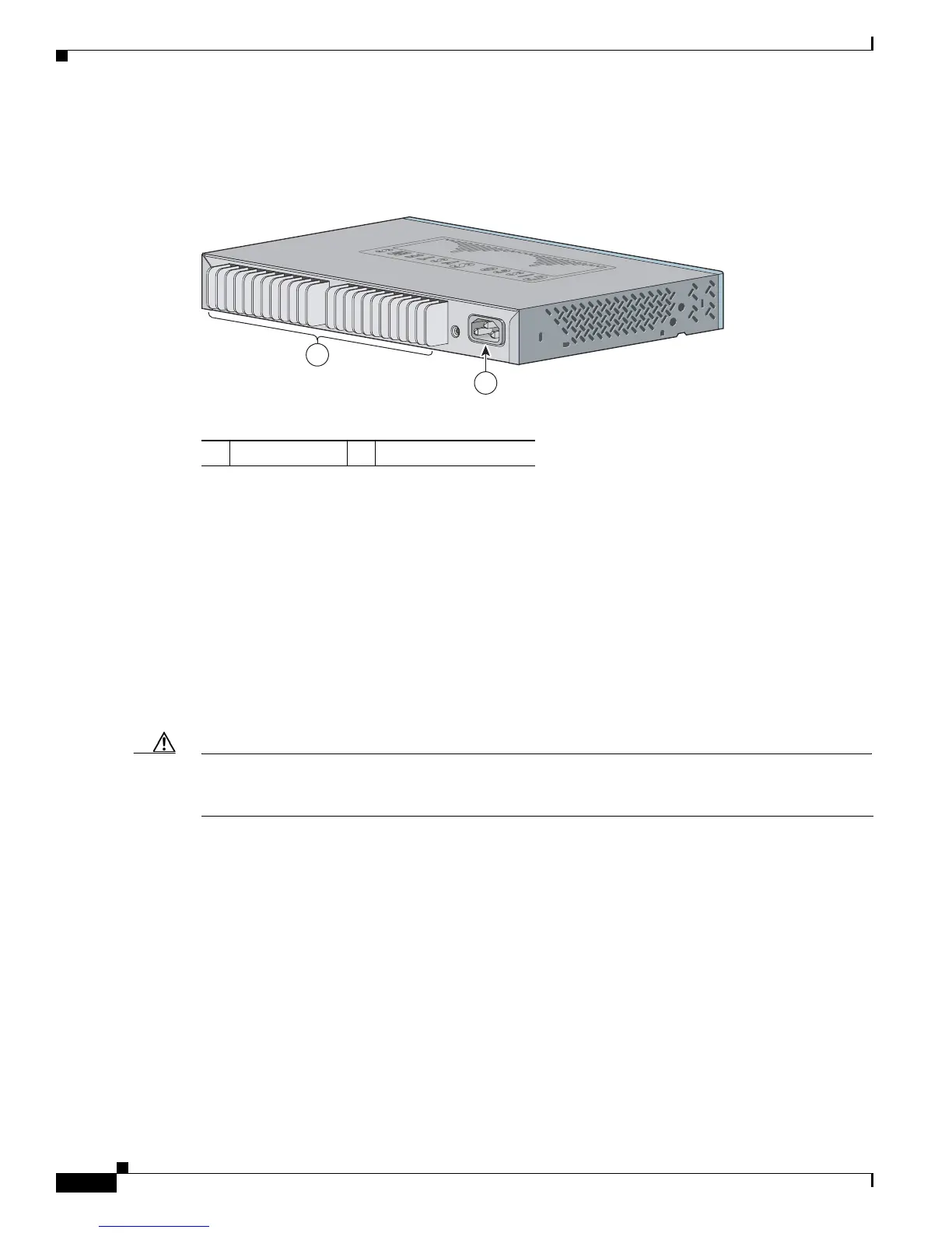
The Catalyst 3560-8PC and Catalyst 3560-12PC-S rear panels have an AC power connector and heat
sinks. (See Figure 1-18.)
Figure 1-18 Catalyst 3560-8PC and Catalyst 3560-12PC-S Switch Rear Panel
Internal Power Supply
An internal power supply powers the switch. The internal power supply is an autoranging unit that
supports input voltages between 100 and 240 VAC. Use the supplied AC power cord to connect the AC
power connector to an AC power outlet.
DC Power Connector
The Catalyst 3560V2-24TS-SD has an internal DC-power converter. It has dual feeds (A and B) that are
diode-OR-ed into a single power block. For installation instructions, see Appendix C, “Connecting to
DC Power.”
Caution You must connect the Catalyst 3560V2-24TS-SD switch only to a DC-input power source that has an
input supply voltage from –36 to –72 VDC. If the supply voltage is not in this range, the switch might
not operate properly or might be damaged.
1 Heat sinks 2 AC power connector

 Loading...


