B-3
Catalyst 3560 Switch Hardware Installation Guide
OL-6337-07
Appendix B Connector and Cable Specifications
Connector Specifications
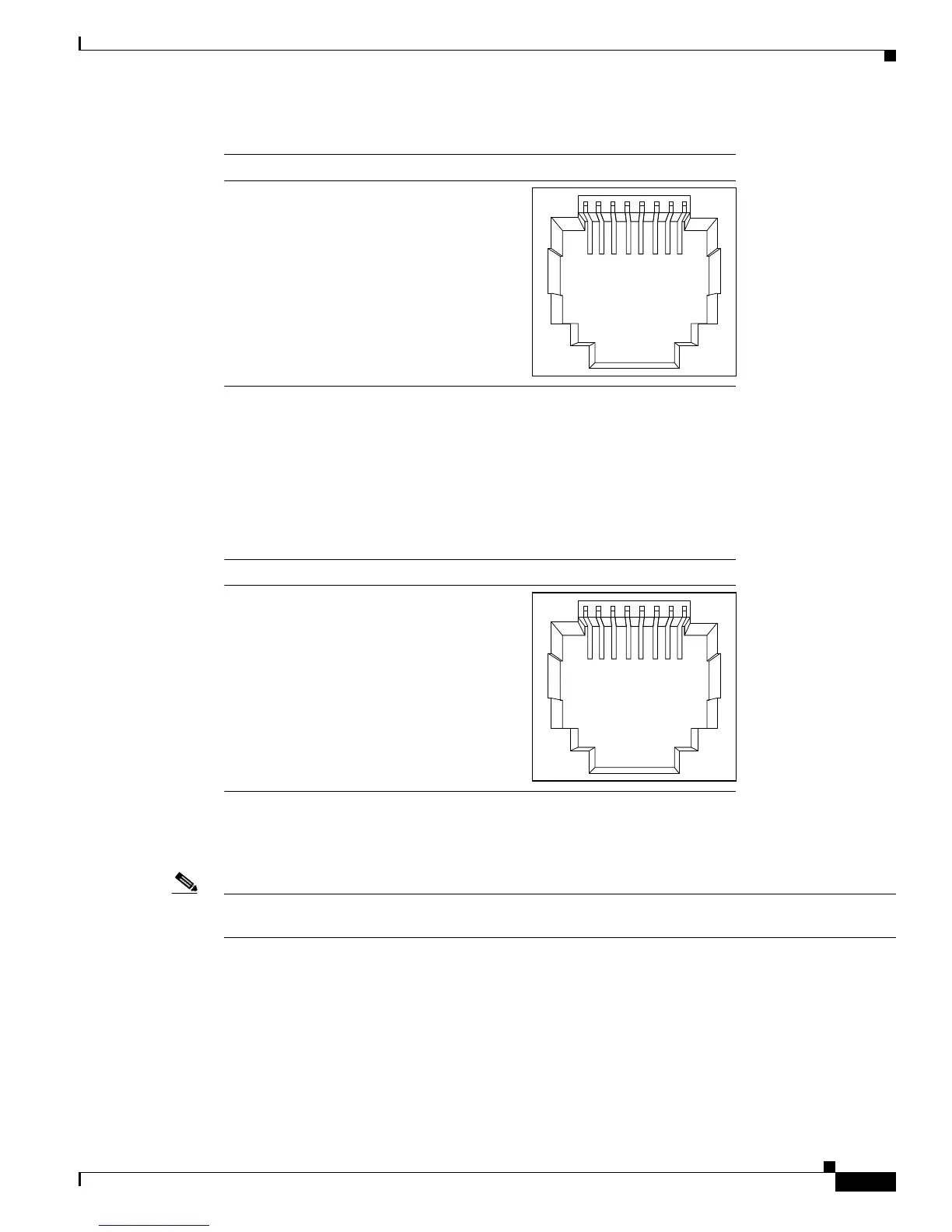
Figure B-4 Copper SFP Module RJ-45 Connector
Dual-Purpose Ports
The Ethernet port on a dual-purpose port uses standard RJ-45 connectors. Figure B-5 shows the pinouts.
Figure B-5 10/100/1000 Port Pinouts
The SFP module slot on a dual-purpose port uses SFP modules for fiber-optic and copper uplink ports.
See the Catalyst 3560 release notes for a list of supported SFP modules.
Note The auto-MDIX feature is enabled by default. For configuration information for this feature, see the
switch software configuration guide or the switch command reference.
Console Port
The console port uses an 8-pin RJ-45 connector, described in Table B-2 and Table B-3. The
RJ-45-to-DB-9 adapter cable connects the console port of the switch to a console PC. You need an
RJ-45-to-DB-25 female DTE adapter (ACS-DSBUASYN=) to connect the switch console port to a
terminal. For console port and adapter pinout information, see Table B-2 and Table B-3.
60915
231 45678Pin Label
1
2
3
4
5
6
7
8
TP0+
TP0-
TP1+
TP2+
TP2-
TP1-
TP3+
TP3-
60915
231 45678Pin Label
1
2
3
4
5
6
7
8
TP0+
TP0-
TP1+
TP2+
TP2-
TP1-
TP3+
TP3-

 Loading...


