Chapter 4 Printer Adjustments
53
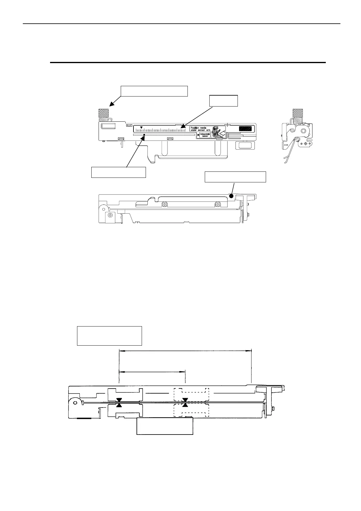
4 Adjustable Sensor (For CLP-7201e)
Note: The adjustable sensor is optional for CLP-7202e.
Top view
Side view
Operating procedure
1. Measure your required detection position beforehand, using the scale on the upper guide
rail. Move the adjustable sensor to the required detection position by tuning the adjustable
knob; it is useful to align the mark (yellow) on the top of the adjustable sensor with the
scale showing the required detection position.
For the movable range of the adjustable sensor, see figure below.
2. Set media with liner. Then close the upper guide rail and set the voltage to 3V.
Note: For voltage setting, see Section 5 System Maintenance Mode, Chapter 2.
Side view
Ad
ustable knob
Mark
ellow
Upper guide rail
Left end of media:
0 mm
118 mm (max. media width)
59 mm (sensor usable range)
djustable senso
movable range
4 Adjustable Sensor (For CLP-7201e)
Scale