- 5 -
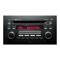
PN-2280D
pin 77 : XIN : IN : Connects a crystal.
pin 78 : CE : IN : Chip enable signal input.
pin 79 : VDD : - : Power supply terminal.
pin 80 : RESET : IN : Reset signal input. Negative logic.
Table 1. Mechanism mode switch
Mechanism mode Bit1 Bit2 Bit3
Eject H H H
Loading H H L
Stop L H L
Fwd-FF ( Rev-Rew ) L L H
Fwd-Rew ( Rev-FF ) H L L
Fwd-Play H L H
Rev-Play L H H
Table 2. Power motor control
Mechanism mode P1 P2
Loading, Head advance H L
Eject, Head retreat L H
Keeping a state H H
Stop L L
3.Key Matrix
Table 3. Key Matrix table
KR 0 KR 1 KR 2 KR 3 KR 4
pin25 pin24 pin23 pin22 pin16
KS 0 FM/ Tape Seek up/ Seek down/
pin9 AM Scan up Scan down
KS 1 M1 M2 M3
pin10 APS Rew APS-FF Prog
KS 2 M4 M5 M6 CD/
pin11 DOLBY REW FF CHG
KS 3 Sound Tune up/ Tune down/
pin12 Disc up/ Disc down/
Sound up Sound down
KS 4 Mode Seek up/ Seek down/ ILL on ST on
pin13 APS up APS down
( Tr SW ) ( Tr SW ) ( Tr SW ) ( Tr SW ) ( Tr SW )
KS 5 BAND 0 BAND 1 BAND 2 Clock on/off 2SP=1
pin14 Ref.Table4 Ref.Table4 Ref.Table4 on=1 4SP=0
( Di SW ) ( Di SW ) ( Di SW ) ( Di SW ) ( Di SW )
Table 4. Diode switch
Diode switch BAND 0 BAND 1 BAND 2
Normal volume 0 1 0
BOSE6V volume 0 0 1
0 = open , 1 = shorted with diode
■μPD78002BGC-650-AB8 052-5018-03 PMCD Controller
1. Outward Form : 64pins, QFP
2. Terminal Description
pin 1 : SRQ : O : C-BUS service request signal output. Negative
logic.
pin 2 : CHU-SW : IN : CD disc chucking signal input. Negative logic.
pin 3 : N.C. : O : Not in use.
pin 4 : N.C. : O : Not in use.
pin 5 : N.C. : O : Not in use.
pin 6 : B : IN : Photo sensor input to detect CD disc status.
pin 7 : A : IN : Photo sensor input to detect CD disc status.
pin 8 : C : IN : Photo sensor input to detect CD disc status.
pin 9 : VSS : − : Ground.
pin 10 : MCCW : O : Loading motor control output. Ref. Table 1.
pin 11 : MCW : O : Loading motor control output. Ref. Table 1.
pin 12 : N.C. : O : Not in use.
pin 13 : N.C. : O : Not in use.
pin 14 : N.C. : O : Not in use.
pin 15 : N.C. : O : Not in use.
pin 16 : N.C. : O : Not in use.
pin 17 : N.C. : O : Not in use.
pin 18 : N.C. : O : Not in use.
pin 19 : N.C. : O : Not in use.
pin 20 : ACDT : IN : Not in use.
pin 21 : XRST : O : Reset signal output to CXD2548. Negative
logic.
pin 22 : CLOCK : O : Clock signal output to CXD2548. Negative
logic.
pin 23 : XLAT : O : Latch signal output to CXD2548. Negative
logic.
pin 24 : VSS : − : Ground.
pin 25 : DATA : O : Serial data output to CXD2548.
pin 26 : SCLK : O : Serial clock output to read data from CDIC.
Negative logic.
pin 27 : N.C. : O : Not in use.
pin 28 : SENS : IN : CD status signal detect. Negative logic.
pin 29 : SQSO : IN : Serial data input to read out SUB-Q-data from
CXD2548. Negative logic.
pin 30 : N.C. : O : Not in use.
pin 31 : SQCK : O : Clock signal output to read SUB-Q-data from
CXD2548. Negative logic.
pin 32 : SYSM : O : Mute signal output. Negative logic.
pin 33 : N.C. : O : Not in use.
pin 34 : N.C. : O : Not in use.
pin 35 : RST : IN : Reset signal input. Negative logic.
pin 36 : SCOR : IN : Sub code synchronization.
pin 37 : ACC-CNT : IN : C-BUS ACC CNT input terminal. If "L" is input
during disc rotation (Play,FF,FB,Search), it
enters into power saving mode after disc rota-
tion stops. If "L" is input in Loading or Ejecting,
it enters into power saving mode after comple-
tion of motion.
pin 38 : N.C. : O : Not in use.
pin 39 : N.C. : O : Not in use.
pin 40 : VDD : − : Power supply voltage.
pin 41 : X2 : O : Connect ceramic resonator.
pin 42 : X1 : IN : Connect ceramic resonator.
pin 43 : IC0 : − : Connected to ground.
pin 44 : XT2 : O : Not in use.
pin 45 : XT 1/P04 : − : Connected to ground.
pin 46 : IC1 : − : Connected to ground.
pin 47 : N.C. : O : Not in use.
pin 48 : SYS-1 : O : Output terminal to control system power 1.
Control terminal to switch between power for
loading motor driver IC and that for CD driver
IC (+8V).
Outputs "H" when ACC-CNT input terminal is
"H" while this micro computer is regular mo-
tion.
Outputs "L" when ACC-CNT input terminal is
"L" while this micro computer is in power sav-
ing mode.
Power ON in "H" .Power OFF in "L" .
pin 49 : SYS-2 : O : Output terminal to control system power 2.
Control terminal to switch power to CDIC (+5V).
Turns this terminal to "H" in CD PLAY. Other
than that, "L" .
Power ON in "H" . Power OFF in "L" .
pin 50 : N.C. : O : Not in use.
pin 51 : N.C. : O : Not in use.
pin 52 : N.C. : O : Not in use.
pin 53 : N.C. : O : Not in use.
pin 54 : N.C. : O : Not in use.
pin 55 : IC2 : − : Connected to ground.
pin 56 : IC3 : − : Connected to ground.
pin 57 : K-0 : I/O : Key input in test mode. Function as output ter-
minal in C-BUS communication mode.
pin 58 : K-1 : I/O : Key input in test mode. Function as output ter-
minal in C-BUS communication mode.
pin 59 : K-2 : I/O : Key input in test mode. Function as output ter-
minal in C-BUS communication mode.
pin 60 : K-3 : I/O : Key input in test mode. Function as output ter-
minal in C-BUS communication mode.
pin 61 : K-4 : IN : Terminal to detect Test mode starting. Checks
the terminal logic during hard reset and ACC
ON (during ACC-CNT = "H" ) just after start of
program.
Outputs "H" in C-BUS communication mode.
Outputs "L" in Test mode.
pin 62 : SI : IN : C-BUS serial data input.
pin 63 : SO : O : C-BUS serial data output.
pin 64 : SCK : IN : C-BUS serial data clock input.
Table 1
Loading Eject Brake Stop
MCW HLHL
MCCW L H H L
 Loading...