14
MODELS
DRIVE
SHAFT
BOLT
SIZE
/GRADE
TIGHTEN-
ING
TORQUE
ft-lbs
C32H0-
UFAC10
C32H0-
UFAC18
C32H0-
UFAC20
C32H0-
UFAC28
C32H0-
UFAC30
C32H0-
UFAC38
C32H0-
UFAC40
C32H0-
UFAC48
C32H0-
UFAC50
C32H0-
UFAC58
C32H0-
UFAC60
C32H0-
SC2390A
M16,
Class 10.9
(Metric)
(Hi-
Tensile)
210 - 220
(285 - 298)
(see note #2,
#3)
Note 1 – It is recommended that a medium strength
threadlocker (Loctite 243–blue) be used in the
assembly and of all hardware. This may be purchased
as part number C126758, 50ml bottle.
Note 2 – 4 of the hi-tensile bolts and/or nuts, that are
used to connect the driveshaft to the drive disc and that
connect the driveshaft to the pump companion flange,
will require a “crow’s foot” wrench attached to a
standard torque wrench to apply the required tightening
torque. A standard socket will not work due to
proximity of the bolts and/or nuts with the driveshaft
yoke. The tightening torque values listed for these
bolts and/or nuts have been corrected for using a
“crow’s foot” adapter which extends the standard
torque wrench’s length.
Note 3 – For the high torque required for these nuts, it
is recommended that a boxed-end crows foot be used.
The following steps describe the proper way to check
alignment. A small pocket scale or ruler with
millimeter markings is recommended to make all
measurements.
Before removing the drive shaft guard, disconnect the
negative battery cable from both batteries.
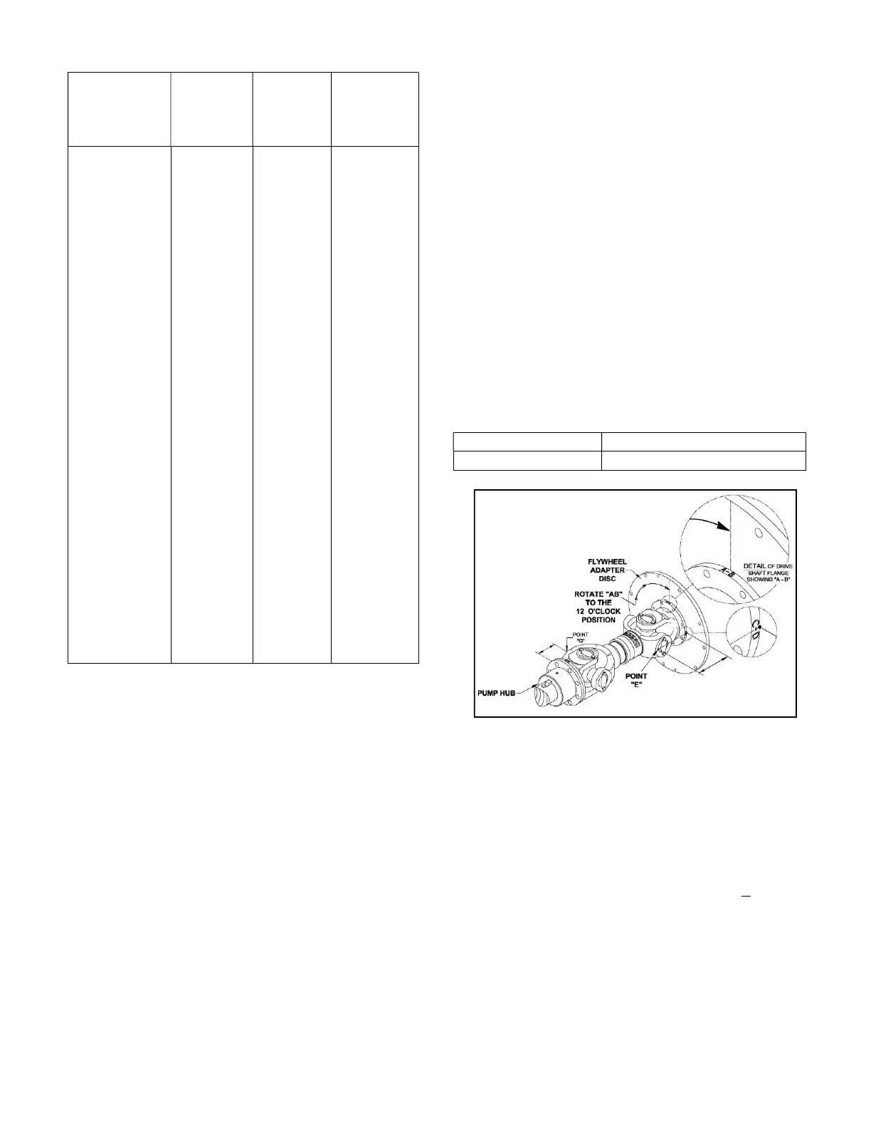
A) To check the Horizontal Parallel Offset, the
driveshaft must be in the proper orientation.
1. Rotate the shaft so the reference “AB” on the
flywheel adapter disc or the circumference of
the drive shaft flange (against the flywheel
adapter disc) is in the 12 o’clock position
shown on Figure #7a.
2. Measure from the face of the flywheel adapter
disc to point E. (Point E is on the bearing bore
as shown in Figure #7a). This measurement
must be:
142.5 + 1.5mm SC2390A
Figure #7a
B) With the driveshaft in the same orientation as the
previous step (Step A), check the Horizontal
Angular alignment of the shafts.
1. Measure from the mating surface of the
companion hub to point G shown on figure
#7b. (Point G is the furthermost point on the
bearing bore). This measurement must be
equal to the measurement at point E + 0.5 mm.
 Loading...