43
(Note: There is no engine mounted High
Coolant Temperature switch to jumper
across).
Alarm 4: Over crank:
Lift and hold the OVERSPEED RESET
SWITCH for 5 seconds prior to initiating the
6 crank cycles from the fire pump controller.
Ensure that the OVERSPEED RESET
SWITCH is held for the entire duration of
each of the 6 crank attempts. Each time,
while the engine is resting for 15 seconds
between cranking attempts, release the
OVERSPEED RESET SWITCH for 3
seconds. Before the engine cranks again,
activate the OVERSPEED RESET SWITCH
and continue holding throughout the crank
attempt, releasing in between each attempt.
NEVER shut off the fuel supply to the
engine to prevent it from starting. Shutting
off the fuel supply will cause an air lock
condition in the fuel system and possibly
cause fuel system component damage.
Alarm 5: Low Engine Coolant Temperature:
With engine at rest, lift low coolant
temperature switch for 25 seconds.
Alarm 6: ECM Warning: Lift the
OVERSPEED RESET SWITCH for 2
minutes with engine not running to verify
ECM Warning Alarm; note engine will
automatically switch to alternate ECM.
Alarm 7: ECM Failure: After ECM Warning
Alarm has been tested, continue lifting
OVERSPEED RESET SWITCH for
additional 2 minutes with engine not running
to verify ECM Failure Alarm. After
activation of both ECM Warning and Failure
Alarms, activate the ECM Failure Reset
Switch inside the engine control panel.
3.5.5 Battery Requirements
All Clarke engine models require 8D batteries, as
sized per SAE J537 and NFPA20. The battery
should meet the following criteria:
Cold Cranking Amps (CCA @ 0°F): 1200
Reserve Capacity (minutes): 430
Refer to Clarke drawing C131885 (see
www.clarkefire.com) for additional information
on Clarke supplied batteries.
3.6 ENGINE SPEED ADJUSTMENT
All governor and speed control functions are
programmed into each ECM at the factory. During
Start-Up Inspection, some minor speed adjustment
may be required.
To adjust the speed of the engine:
A. Start the engine by following the “To Start
Engine” Procedure in this manual.
B. Let the engine warm-up.
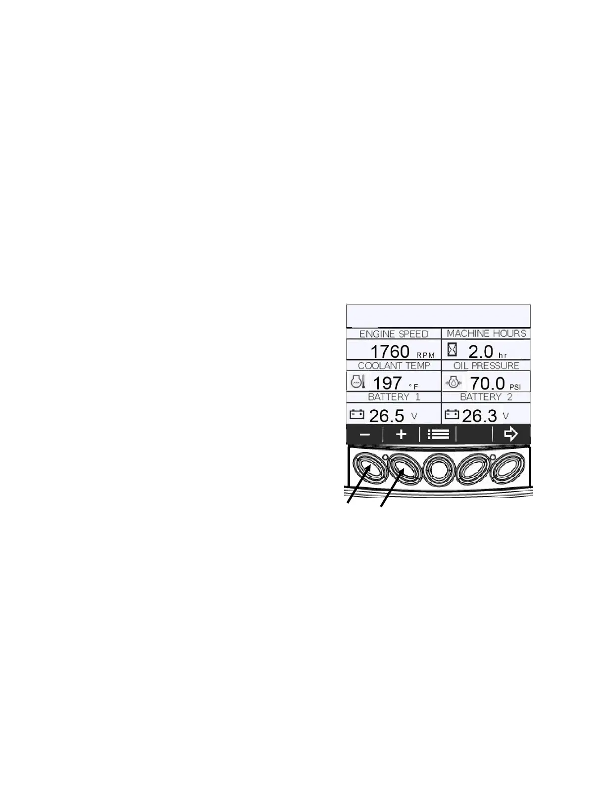
C. While observing the tachometer on the
Powerview Gauge, from the 6-up display,
press the appropriate bump switch on the
gauge. (Refer to Figure # 23).
D. Speed will increment by 5 rpms each time +
or – is pressed.
E. Stop engine by following “To Stop Engine”
Procedure in this manual.
F. Switch to Alternate ECM and repeat steps A
through D.
G. Stop engine by following “To Stop Engine”
Procedure in this manual.
H. Switch back to Primary ECM.
Figure #23
4.0 MAINTENANCE SCHEDULE
4.1 ROUTINE MAINTENANCE
NOTE: The following Routine Maintenance schedule
is based on an engine usage rate not exceeding 2
hours per month. For UL/FM engine models, also
refer to NFPA25.
LEGEND:
Check
Clean
Replace
o Lubricate
Bump
Switches