17
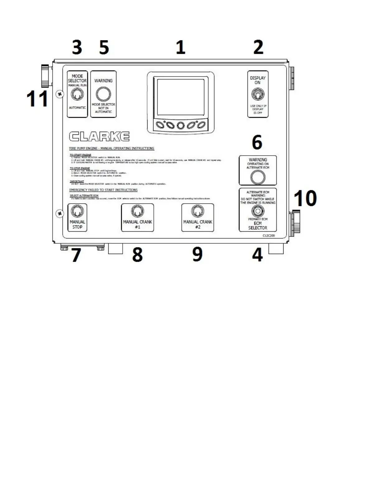
Figure #8
1 - PowerView Gauge
2 - Momentary Display On Switch
3 - Automatic/Manual Mode Selector Switch
4 - ECM Selector Switch
5 - Manual Mode Indicator Warning Light
6 - Alternate ECM Indicator Warning Light
7 - Manual Stop Switch
8 - Manual Crank Switch – Battery #1
9 - Manual Crank Switch – Battery #2
10 – Service Tool Connector
11 – PLD Harness Connector
2.6.3 Describing Engine Gauge Panel
2.6.3.1 ECM Selector Switch and Primary/Alternate
ECM
Clarke UL/FM Engines come equipped with dual
ECMs and an ECM Selector Switch on engine gauge
panel. (Item #4). Default position of ECM selector
switch is to the Primary ECM. In the event of a
failure of the Primary ECM, where-by the engine shuts
down or will not start, it will become necessary to
manually switch to the Alternate ECM position. When
the ECM Selector Switch is positioned to the Alternate
ECM position a warning light will illuminate at the
engine gauge panel. Also, the main controller will
display a warning light and an audible alarm. The
engine should then be re-started manually. (See
section 2.6.1). Contact a Clarke Authorized Service
Dealer immediately when this situation occurs to
troubleshoot. (See section 7.0).
Information displayed on the PowerView diagnostic
gauge will come from either the Primary or Alternate
ECM depending upon the position of the ECM
Selector Switch.
If a fault code(s) is displayed and comes from the
Primary ECM, and then the ECM selector switch is
moved to the Alternate ECM position, it may be