15
Figure #7b
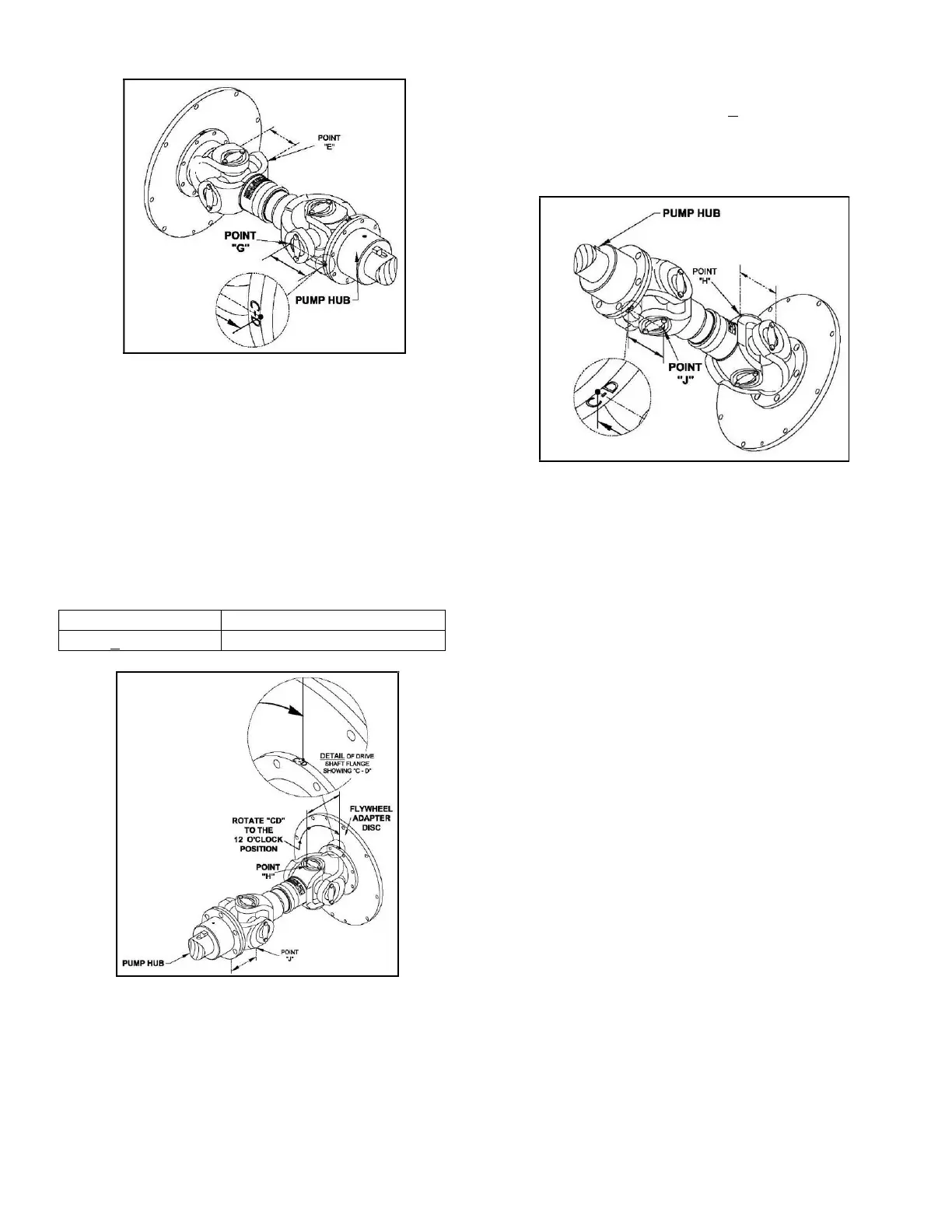
C) To check the Vertical Parallel Offset, the
driveshaft must be re-orientated.
1. Rotate the shaft 90
○
so the reference “CD” on
the flywheel adapter disc or the circumference
of the drive shaft flange (against the flywheel)
is in the position shown on Figure#7c.
2. Measure from the face of the flywheel adapter
disc to point H. (Point H is the furthermost
point on the bearing bore diameter). The
measurement must be:
Figure #7c
D) With the driveshaft in the same orientation as the
previous step (Step C), check the Vertical
alignment of the shafts.
1. Measure from the mating surface of the pump
companion hub of the drive shaft to point J as
shown in figure #7d. (Point J is the same as
point G, with the driveshaft rotated 90
o
). This
measurement must be equal to the
measurement at point H + 1 mm.
Re-install all guards and grease fittings before
reconnecting the battery cables.
Figure#7d
DRIVESHAFT MAINTENANCE
1. To service the driveshaft, disconnect the
negative battery cables, remove the top of
guard and set aside.
2. Rotate engine shaft manually so the u-joint
grease fittings are accessible.
3. Using a hand-held grease gun with N.L.G.I.
grade 1 or 2 grease position on grease fitting.
Pump with grease until grease is visible at all
four cap seals.
4. Verify all driveshaft connecting bolts remain
tight. Re-torque per 2.4.1 if necessary.
5. Reinstall top of guard and connect negative
battery cables.
2.5 WEEKLY TEST
An experienced operator should be present during the
weekly test.
NOTE: This engine is designed to operate at rated load
conditions. For testing purposes the engine can be run
at lower load (lower flow) conditions. Running times
in any one period should not exceed a maximum of 30
minutes. Before starting the engine make sure of the
following:
1) The operator has free access to stop the engine
in an emergency.
2) The plant room ventilation ducts are open and
the engine has good access for air.