6
07610-004-64-85-A
INSTRUCTIONS
INSTALLATION
WATER SUPPLY
CONNECTIONS:
WATER HARDNESS
LOWER THAN 3 GPG
PRESSURE
REGULATOR
SHOCK ABSORBER
CONNECTING THE
DRAIN LINE
If water hardness tests at 3 GPG or lower, connect the machine water line (installed
at the factory, 3/4" Male GHT connected to a true 1/2” ID line) to the facility water line.
A water shut-o valve should be installed in the water line between the facility supply
and the machine to allow access for service. The water supply line must be capable
of the minimum “ow” pressure at the recommended temperature indicated on the
data plate.
The manufacturer has an optional Pressure Regulating Valve (PRV) to accommodate
areas where water pressure uctuates or is higher than the recommended pressure.
Take care not to confuse static pressure with ow pressure. Static pressure is line
pressure in a “no ow” condition (all valves and services are closed). Flow pressure is
the pressure in the ll line when the valve is open during the cycle. See the Plumbing
Options page.
A shock absorber (not supplied) should be installed on the incoming water line. This
prevents water hammer or hydraulic shock—induced by the solenoid valve as it
operates—from causing damage to the equipment. See the Plumbing Options page.
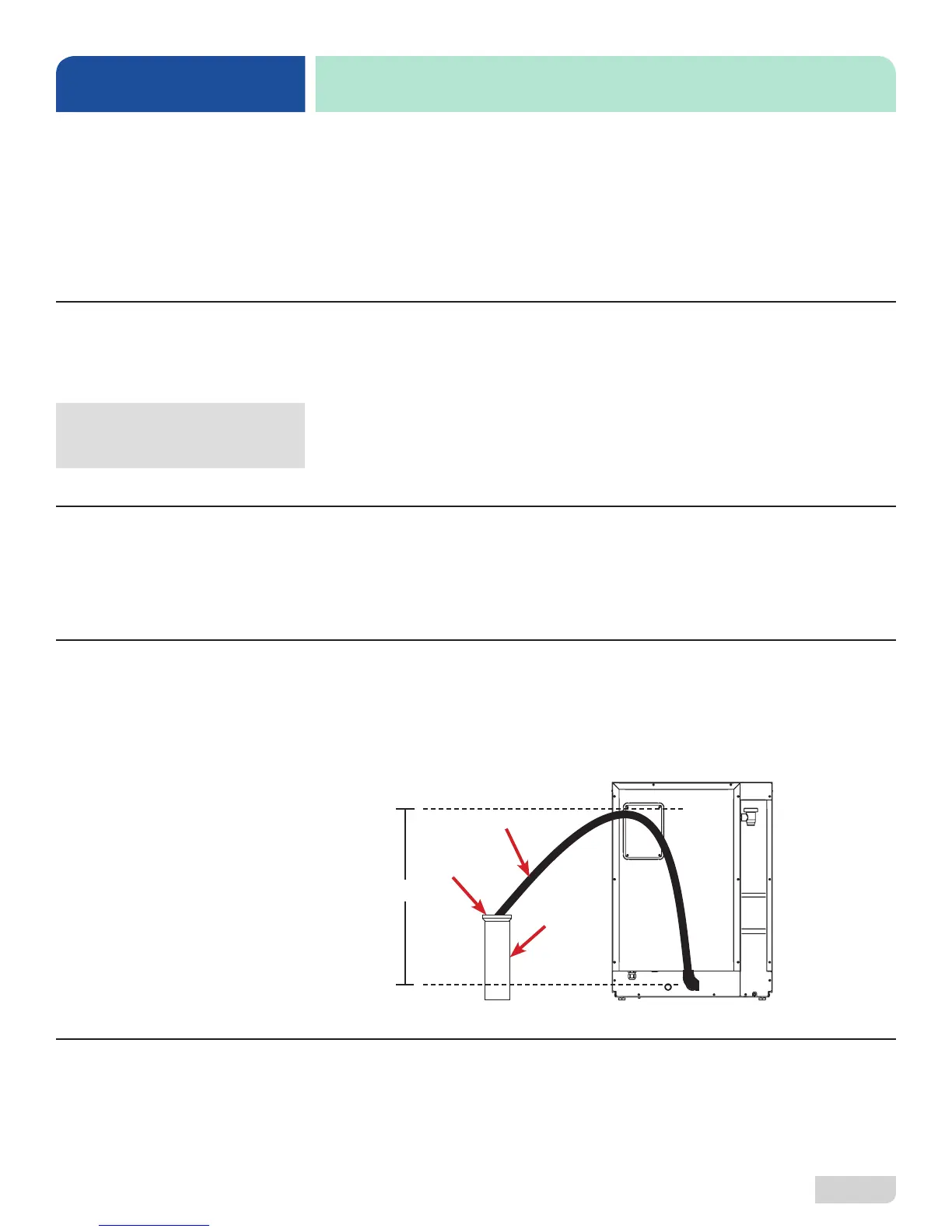
The machine has a pumped (pressure) drain capable of pumping waste water to
a height of 24” above the machine's drain pump and is supplied with a drain hose.
There must be an air-gap between/around the machine drain hose and the oor drain
or sink. The oor drain or sink must be at least 1.5 times larger than the machine drain
hose. If a grease trap is required by code, it should have a ow capacity of 12 GPM.
After installing the incoming water line and the drain line, slowly turn on the water
supply to the machine. Check for any leaks and repair as required. All leaks must be
repaired before operating the machine.
Take care not to confuse
static pressure with
ow pressure!
PLUMBING CHECK
≤24”
Air-gap
Floor Drain
or Sink
Drain Hose