IC1 and IC2 Intercom Controls and Indicator Lights:
The IC1 portion of this area of the panel is for Intercom Channel 1, and the IC2 portion is for Intercom
Channel 2. Their operation is identical.
● The SELECT button is used to select 2-Wire or 4-Wire or both.
● The 2-W indicator light will come on red (muted) if wired intercom power is not detected at the
2-W connector on the rear panel of the base station. The 2-W indicator light will come on green if 2-
W equipment which supplies power is plugged into the 2-W connector on the rear panel of the base
station, or if the respective bypass jumper inside the unit has been set.
● The INPUT controls are used to adjust the audio levels going to beltpack, all-in-one headset or a
local headset coming in from 2-W and 4-W equipment connected to the base station.
● The OUTPUT controls are used to adjust the audio levels coming in from beltpacks and all-in-one
headsets or a local headset, as it goes out to 2-W and 4-W equipment connected to the base station.
● The AUTO NULL button is used to eliminate echo caused by mismatched line characteristics of an
external 2-W system. CAUTION: Before pressing the AUTO NULL button, be sure there are no
open microphones on the wired system. Use a pen or similar pointed object to press and hold the
AUTO NULL button for 2 seconds.
NOTE: If you are not connecting other equipment, go on to System Operation, section 3, page 14.
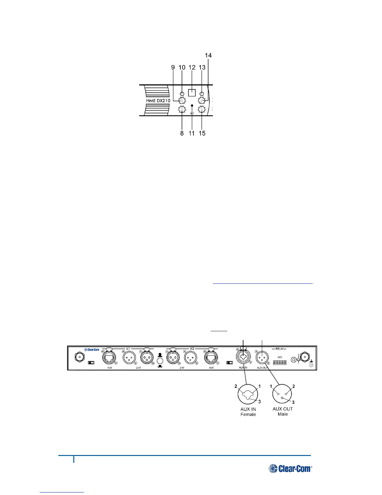
2.5 Interfacing with Auxiliary Audio Equipment
ISO Audio can be routed to the AUX OUT connector for page or stage announce.
● If using auxiliary audio equipment such as another intercom, a CD player, etc., connect its output
cable connector (male) to the AUX IN connector (#48), and/or its input cable connector (female) to
the AUX OUT connector (#49).
The cable connectors must be 3-pin
XLR type for balanced +20dBu Pin 1 = Ground
maximum audio input/output, with Pin 2 = Audio +
the following pin connections: Pin 3 = Audio –
 Loading...