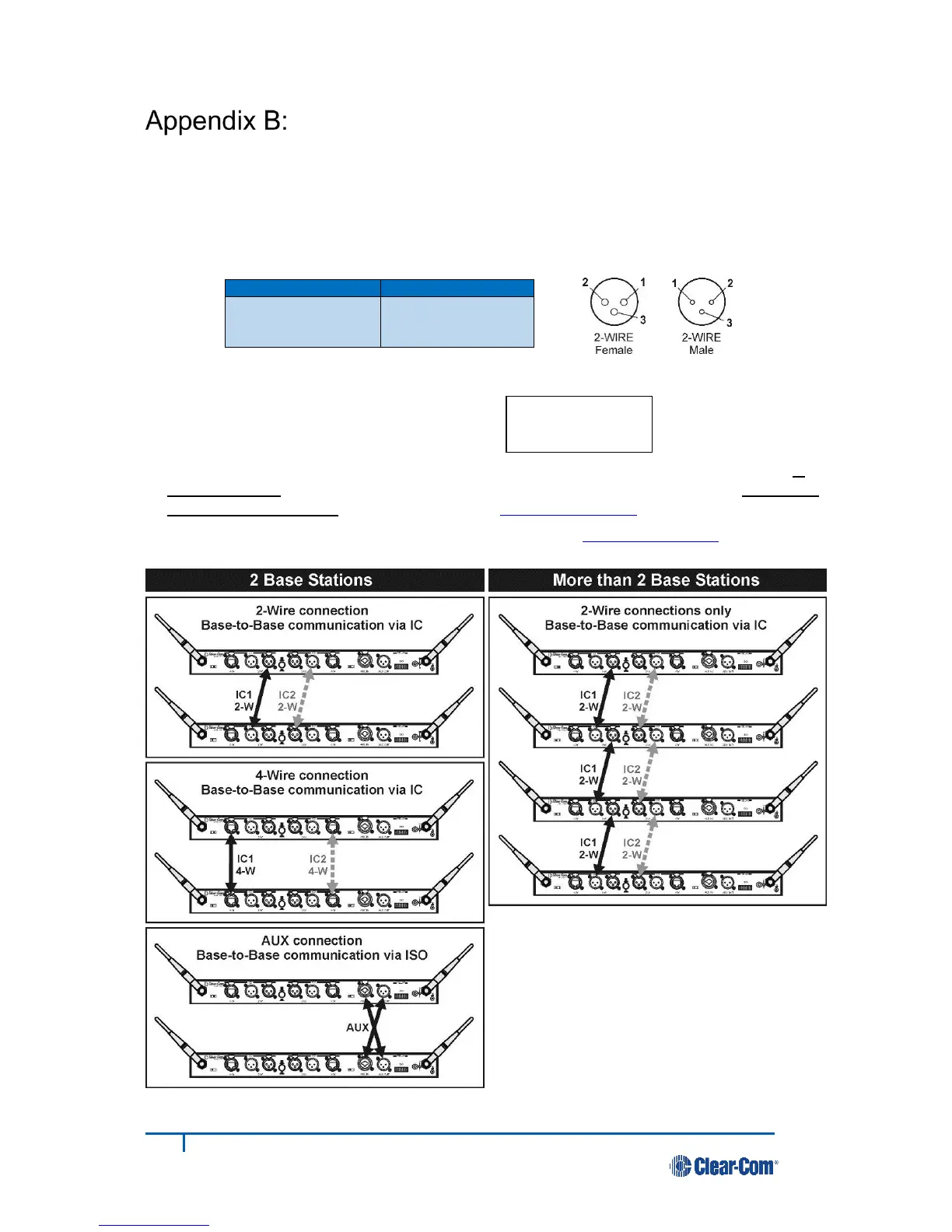
Multiple Base Station Daisy-Chaining
Two or more DX210 base stations can be “daisy-chained” using the 2-W connector ports on the rear panels
of each base station (following Clear-Com
®
/ RTS
®
standards), or two base stations (not more) can be “daisy-
chained” together with cables connected to the 4-W or AUX connectors.
NOTE 1: DX210 does not provide 2-wire line power, therefore, 2-wire power bypass must be used.
NOTE 2: For AUX type daisy-chaining, the cable connectors must be 3-pin XLR.
● If using 4-wire connection, use cable with In/Out
crossed, as shown to the right.
(An Ethernet crossover cable will not work.)
● If using 2-Wire connections, open each base station and set jumpers JP1 (IC1) and/or JP2 (IC2) in
all base stations to ON for power detect bypass. Set jumpers JP5 (IC1) and/or JP6 (IC2) in only one
base station per channel for termination. Refer to Appendix C, page 23.
● Perform base station registration for each base station. Refer to Appendix D, page 24.
 Loading...