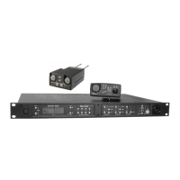
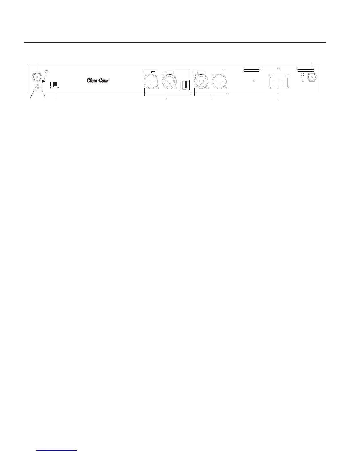
Controls and Connections - Rear Panel
1. Receive Antenna - Female “TNC” Connector. Color band
on antenna must match color dot on base station.
2. Transmit Power Switch – HIGH = Transmitter at full
power. NORMAL = Transmitter 10dB below full power.
3. Transmit ON/OFF Switch – Turns the transmitter on or off.
4. I/C Select Switch – Set to the appropriate 2-wire intercom
type being interfaced to the unit. Set to either Clear-Com
®
,
RTS, or Telex
®
5. Intercom – Interface to wired intercom system.
2-Wire – Male and Female 3-pin XLR connectors
wired in parallel. The connectors are switched to the
appropriate intercom configuration via the I/C Select
Switch.
4-Wire – An RJ-45 type jack compatible with “Ma-
trix” type intercom systems.
6. Auxiliary Input/Output – One 3-pin female XLR input
connector and one 3-pin male XLR output connector.
7. Power – IEC receptacle. Accepts 100 – 240VAC, 50 – 60 Hz
8. Transmit Antenna - Female “TNC” Connector. Color
band on antenna must match color dot on base station.
2-2
PUSHPUSH
1
2
3
4
5
6
7
8
RECEIVE
HIGH
ON
NORM
OFF
TRANSMIT
POWER
I/C
TELEX CLEAR-COM
RTS
INTERCOM
2-WIRE
L
O
O
P
T
H
R
U
4-WIRE
AUXILIARY AUDIO
INPUT OUTPUT
POWER
100-240 VAC 50-60 Hz
TRANSMIT
WBS-670
FCC ID: B5DM516
CANADA 1321231218A
.
MADE IN U.S.A.
R
Intercom Systems
Figure 3
WBS-670 - Rear Panel