Basics of Firetube Operation
1-10
750-91 (revised 2009)
Model CB-LE Packaged Boiler Manual
1.5.6 — Auxiliary Low-Water Cutoff (optional)
Breaks the circuit to stop burner operation if the water level in the boiler drops below the master low-water cutoff
point.
1.5.7 — Safety Valve(s)
Relieves the boiler of pressure higher than the design pressure or a lower pressure, if designated. Relief valves and
their discharge piping are to be installed to conform to ASME Code requirements.
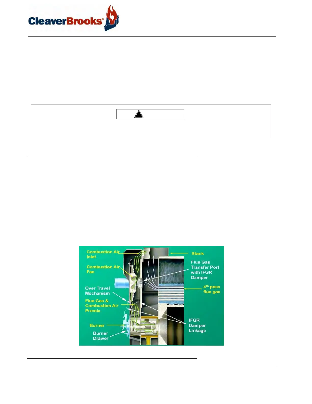
1.6 — IFGR Components
1.6.1 — Flue Gas Transfer Port, IFGR Damper, & Flange Collar
The flue gas transfer port is a tube that allows the flue gasses to travel from the exit of the fourth-pass tubes to the
entrance of the combustion air fan.
The IFGR damper controls the volume of flue gas induced into the combustion air stream. The damper is located
in the flue gas transfer port and is positioned by the control linkage.
1.6.2 — IFGR Damper Linkage
The IFGR damper is positioned by the control linkage. The linkage could consist of a single arm, or it could con-
sist of several arms driven from the jackshaft to provide modulating control.
FIGURE 1-7. Induced Flue Gas Recirculation System
Only properly qualified personnel such as the safety valve manufacturer’s certified representative can adjust or repair
the boiler safety valves. Failure to follow these instructions could result in serious injury or death.
!
Warning