Adjustment Procedures
6-4
750-91 (revised 2009)
Model CB-LE Packaged Boiler Manual
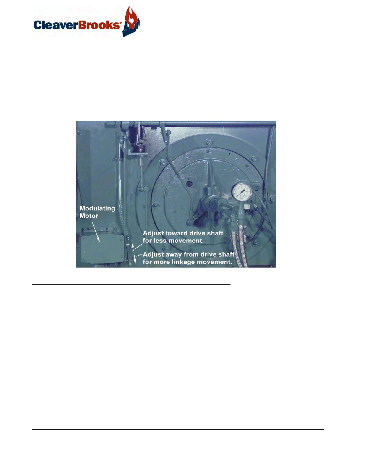
6.3 — Modulating Motor
The modulating motor has a 90º shaft rotation. The motor manufacturer also provides a 160º stroke model for
other applications. If a replacement is obtained from someone other than a Cleaver-Brooks Service or Parts repre-
sentative, it may have an incorrect stroke. To prevent damage, determine the 90º stroke prior to installing a replace-
ment.
The stroke may be determined by powering the motor and connecting terminals R-B to actually determine the
stroke as the motor drives to an open position.
FIGURE 6-3. Modulating Motor
6.4 — Modulating Motor Switches: Low-Fire and High-Fire
The modulating motor contains either one or two internal switches, depending upon application. The micro-
switches are actuated by adjustable cams attached to the motor shaft.
Factory replacement motors have the cams preset. The low-fire start switch is set to make the red and yellow leads
at approximately 8º on motor closing. The high-fire purge air proving switch (located in the modulating motor) is
set to make red and blue tracer leads at approximately 60º on motor opening. Normally, the settings are left as is,
but job conditions may require readjustment. If the cams require adjustment or resetting, follow the instructions in
the manufacturer’s technical manual.