750-91 (revised 2009)
Model CB-LE Packaged Boiler Manual
6-3
6.2 — Linkage: Modulating Motor and Air Damper
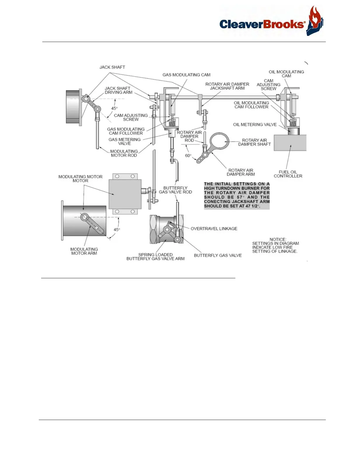
FIGURE 6-2. Complete Linkage Assembly: Combination Gas and Oil
The stop screw in the rotary air damper limits damper travel at both closed (low-fire) and fully opened (high-fire)
positions. The screw is provided so that it is possible to tell, even with the burner in place, whether the damper
rotor is in fully opened or closed position. Rotating the damper clockwise to the stop screw closes the damper.
Rotating the damper counterclockwise to the stop screw opens the damper. Normally, the rate of flow of air
through the damper with the rotor in low-fire position is about one-third of maximum for a standard burner or
one-sixth for a HTB.
The amount of angular movement controlling the rate of air flow is determine by the location of the ends of the
rotary air damper rod in both the jackshaft arm and the air damper arm. When the air damper is in low-fire posi-
tion, the jackshaft arm should be at 45º (47-1/2º for HTB) and the rotary air damper arm should be at an angle of
approximately 60º below the horizontal. This will ensure that the angular movement of the damper starts slowly,
increasing in rate as the high fire position is approached.
Prior to initially firing a boiler it is advisable to check for free movement of the linkage. The damper motor must be
allowed to complete its full stroke and the damper must move freely from low- to high-fire position. Adjustment of
linkage connected to a gas butterfly valve is describe in Section 6.17.