Burner Operation and Control
2-10
750-91 (revised 2009)
Model CB-LE Packaged Boiler Manual
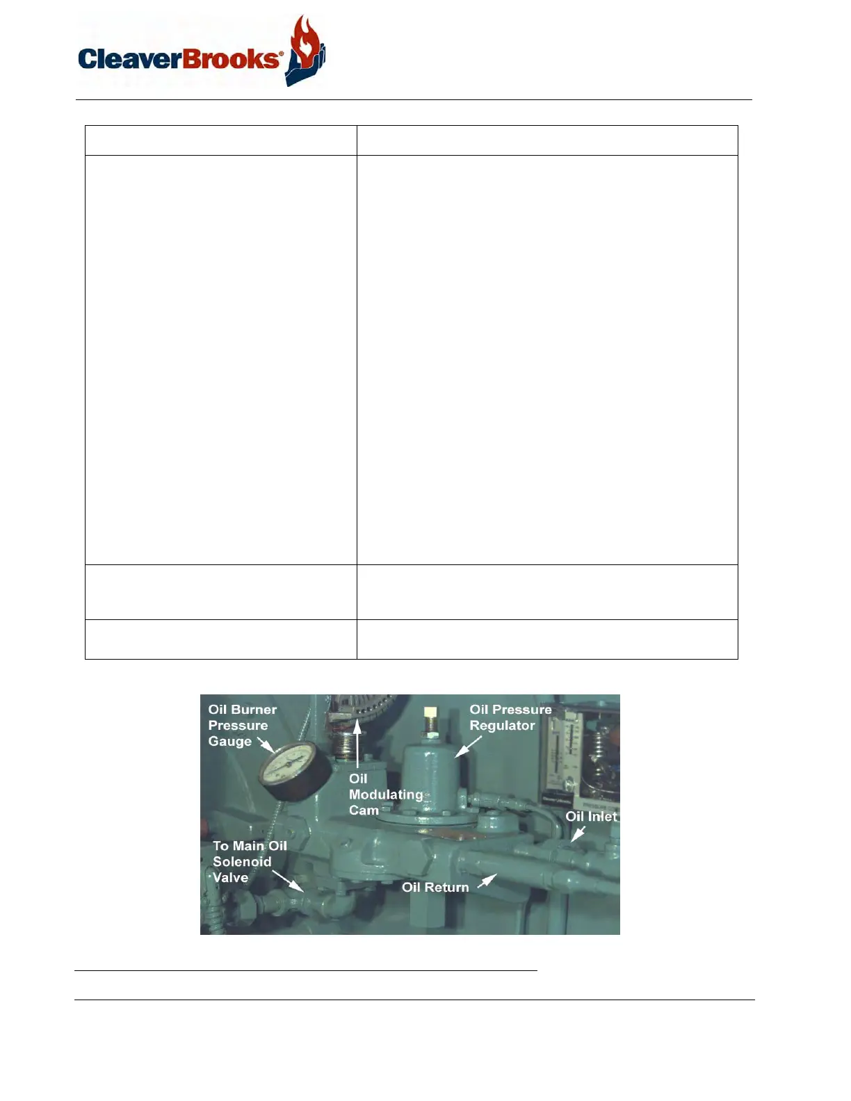
FIGURE 2-5. Oil Control Valve Assembly - Light Oil
Air Pump Module Assembly Provides the compressed air required to atomize the fuel oil for
proper combustion. It is started automatically by the programmer’s
sequence. Components include:
• Air Pump Motor: Drives the air pump and an air cooling fan.
The motor is started and stopped simultaneously with the
forced draft fan motor.
• Air Pump: Provides air for atomization of the fuel oil.
• Air Filter: The filter cleans the air supply prior to entering the air
pump.
• Check Valve: Prevents lubricating oil and compressed air from
surging back through the pump and air filter when the pump
stops.
• Air-Oil Receiver Tank: Holds a supply of oil for lubricating the
air pump. The receiver tank also separates lube oil from the
atomizing air before delivery to the nozzle.
• Lube Oil Level Sight Glass: Indicates the level of lubricating oil
in the air-oil receiver tank.
• Lube Oil Cooling Coil: Cools the lubricating oil before it enters
the air pump. A fan driven by the air pump motor circulates
cooling air over the coil.
• Lube Oil Fill Pipe and Strainer: Used when adding oil to the air-
oil receiver tank.
Low Oil Pressure Switch (optional) Switch contacts open when the fuel oil pressure drops below
selected pressure. Switch will interrupt the limit circuit upon loss of
sufficient fuel oil pressure for correct combustion.
Fuel Oil Pump Transfers fuel oil from the storage tank and delivers it under pres-
sure to the burner system.
Component Description