Adjustment Procedures
6-6
750-91 (revised 2009)
Model CB-LE Packaged Boiler Manual
Separate and independent controls affect modulated firing and burner on-off cycling.
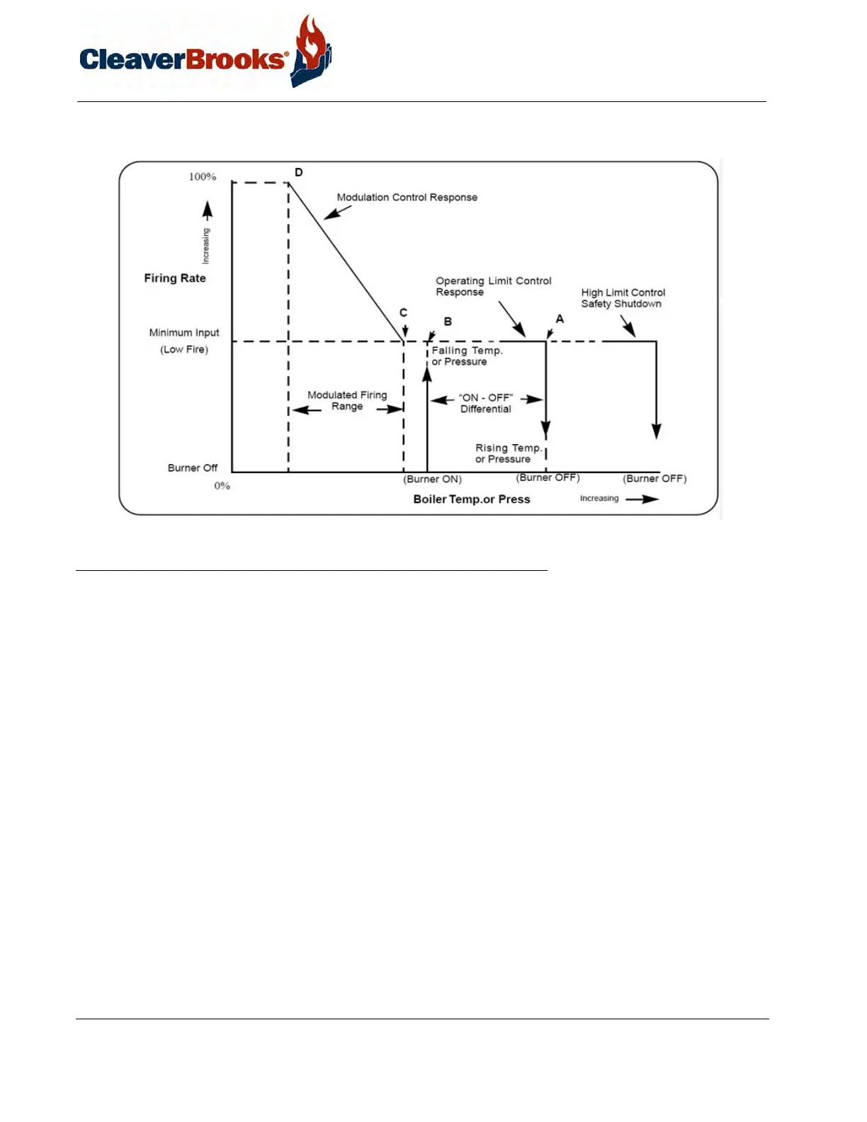
FIGURE 6-4. Firing Graph
The burner will be “on” whenever the pressure or temperature is less than point B (see Figure 6-4) and “off ”
whenever pressure or temperature is greater than point A. The distance between points A and B represents the
“on-off ” differential of the operating limit control.
In normal operation, the burner will shut down whenever the pressure or temperature rises above setting A. At that
point the switch in the operating limit control will open. As the pressure or temperature drops back to B, the oper-
ating limit control closes and the burner will restart. The modulating control will signal the modulating motor to be
in a low-fire position. If the load demands exceed the low fire input potential, the modulating control will increase
the firing rate proportionately as pressure or temperature falls toward point D. The modulating motor will stop at
any intermediate point between C and D whenever the fuel input balances the load requirement.
As the load requirement changes, the firing rate will change accordingly. Thus it is referred to as modulated firing.
Point D represents the maximum firing rate of the burner, or high-fire. In the event pressure or temperature drops
while the burner is firing at high-fire, it indicates that the load exceeds the capacity of the boiler.
The firing graph (Figure 6-4) shows that point B and point C do not coincide. Extreme load conditions could
require the points be closely matched.