28
Geothermal Heat Pump Systems
Tranquility
®
30 Digital (TE) Series IOM - 60Hz HFC-410A
Rev.: 3 Aug., 2012B
Electrical - Low Voltage Wiring
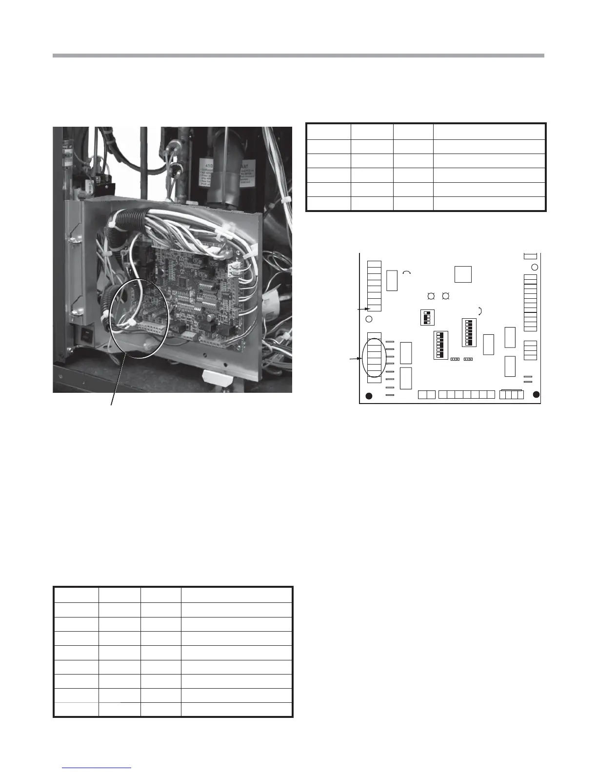
Low Voltage Field Wiring
Accessory Connections
A terminal paralleling the compressor contactor coil
has been provided on the DXM2 control. Terminal “A” is
designed to control accessory devices. Note: This terminal
should be used only with 24 Volt signals and not line voltage.
Terminal “A” is energized with the compressor contactor (see
Figure *).
Alarm
Relay
Comp
Relay
24Vdc
EH1
EH2
P6
Off On
JW3
A
OVR
ESD
C
R
NSB
AL2
JW1
Acc1
Relay
Acc2
Relay
H
COM1
NC1
NO1
COM2
NC2
NO2
P3
CO
RV
RV
LT1
LT1
LT2
LT2
LP
LP
HP
HP
P7
Status
Fault
R
R
CC
CCG
CO
S1
S2
1
12
1
4
e
sU yrot
c
aF
Micro
U1
Off On
P2
COH
COM
AO2
P11
Gnd
T1
P10
T2 T2 T3 T3 T4 T4
T5
P9
T5
T6 T6
A0-1 A0-2
Off On
S3
RV
Relay
CCH
Relay
NC
1 2 3 4
1 2 3 4 5 6 7 8
1 2 3 4 5 6 7 8
Accessory
Relays
Accessory
Terminal
The DXM2 controller includes two accessory relays ACC1
and ACC2. Each relay includes a normally open (NO) and
a normally closed (NC) contact. Accessory relays may be
confi gured to operate as shown in Tables 6 and 7.
Figure 24: Tranquility Low Voltage Field Wiring Table 7: Accessory Relay 2 Confi guration
Table 6: Accessory Relay 1 Confi guration
DIP 2.1 DIP 2.2 DIP 2.3 ACC1 Relay Option
ON ON ON Cycle with fan
OFF ON ON N/A for Residential Applications
ON OFF ON Water valve – Slow opening
ON ON OFF Outside air damper
OFF ON OFF ClimaDry option – Dehumidistat
OFF OFF OFF ClimaDry option – Humidistat
OFF OFF ON N/A for Residential Applications
ON OFF OFF N/A for Residential Applications
All other DIP combinations are invalid
DIP 2.4 DIP 2.5 DIP 2.6 ACC2 Relay Option
ON ON ON Cycle with compressor
OFF ON ON N/A for Residential Applications
ON OFF ON Water valve – Slow opening
OFF OFF ON Humidifi er
ON ON OFF Outside air damper
All other DIP combinations are invalid
Figure *: Accessory Connections