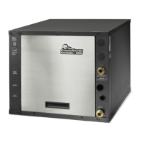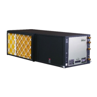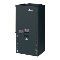
Do you have a question about the ClimateMaster Tranquility Digital and is the answer not in the manual?
| Category | Heat Pump |
|---|---|
| COP | Up to 5.0 |
| Refrigerant | R-410A |
| Type | Water-to-Air |
| Cooling Capacity Range | 24, 000 - 72, 000 BTU/hr |
| Heating Capacity Range | 24, 000 - 73, 000 BTU/hr |
| EER | Up to 30.0 |
| Voltage Options | 208/230V, 460V, 575V |
| Unit Dimensions | Varies by model |
| Unit Weight | Varies by model |
| Stages of Cooling | Single or Two-Stage |
| Stages of Heating | Single or Two-Stage |
Diagnostic chart for troubleshooting compressor contactor issues.
Procedure to check the feedback signal from the pump.
Steps for removing the powerhead from a 1-inch modulating valve.
Using a megohmmeter to test hermetic compressor motor insulation.
Diagram and explanation of the refrigeration circuit in heating mode.
Overview of expansion valve systems and common refrigeration issues.
Procedure for checking auxiliary heat connections and voltage.
Procedure for checking the pump output voltage and communication.
Verifying voltage to the compressor contactor and its resistance.
Checking contactor resistance and voltage.
Procedure for checking the unit's capacitor.
Verifying voltage on the pump power cord.
Steps for replacing the power head of a variable-speed pump.
Verifying voltage at the compressor molded plug.
Checking for 24V at the reversing valve during a cooling call.
Verifying reversing valve operation through the DXM2.
Verifying proper voltage supply to the DXM2 control board.
Explanation and location of the A0-2 jumper for valve/pump configuration.
Checking the position of dipswitches on the DXM2 for proper operation.
Steps for replacing a high pressure water switch.
Turning on the breaker for the unit or auxiliary heat control.
How to perform a static pressure check on the unit.
Finding version information for the thermostat and DXM2 board.
Description of the UltraCheck-EZ™ motor diagnostic tool.
Verifying the settings of dipswitches on the DXM2 board.
Using a magnet to manually shift the reversing valve.
Verifying the line voltage supplied to the blower motor.
Wiring adjustment for modulating valve configuration issues.
Details on Test mode, Retry mode, and configuration options.
Explains factory-set jumpers like A0-2 for valve/pump configuration.
Explains the function of DIP switches for unit setup and operation.
Details DIP switches for accessory relay configuration and fan modes.
Details DIP switches for communications and HWG settings.
Explains fault code 2 for high pressure switch activation.
Explains fault code 3 for loss of charge switch.
Explains fault code 4 for LT1 water coil low temperature.
Explains fault code 5 for LT2 air coil low temperature.
Explains fault code 9 related to swapped thermistors.
Explains fault code 10 related to ECM blower issues.
Explains fault code 11 for low air coil pressure switch.
Explains fault code 12 for low air temperature.
Wiring diagram for DXM2 with internal flow controller.
Wiring diagram for DXM2 with a motorized modulating water valve.
How to access the installer settings menu on the thermostat.
Configuration options for compressor staging (single/multi-stage).
Settings for auxiliary heat operation modes.
Programming options for thermostat scheduling.
Adjusting critical equipment settings in the system configuration.
Setting airflow rates for various operating modes.
Configuring unit family, size, blower type, and loop configuration.
Setting pump control parameters and temperature differentials.
Manually commanding thermostat outputs for troubleshooting.
Viewing status of inputs, switches, and sensor readings.
Viewing the status of dipswitch settings on the connected control.
Displays the five most recent stored fault codes for the control.
Temperature readings recorded at the time of a fault.
Blower/pump speed and valve position readings at fault time.
Status of inputs, switches, and control outputs at fault time.
Dipswitch settings recorded at the time of a fault.
Lists potential causes for recorded faults.


 Loading...