climatemaster.com
57
TSM/TSL Vertical Stack
Rev.: January 18, 2021
THE SMART SOLUTION FOR ENERGY EFFICIENCY
Hose Kit and Chassis Installation
Hose Kit and Chassis Installation - After cabinets are
installed, and walls nished remove the lter and front
blockoff panel. SAVE THESE FOR RE-INSTALLATION
AFTER THE CHASSIS IS INSTALLED!
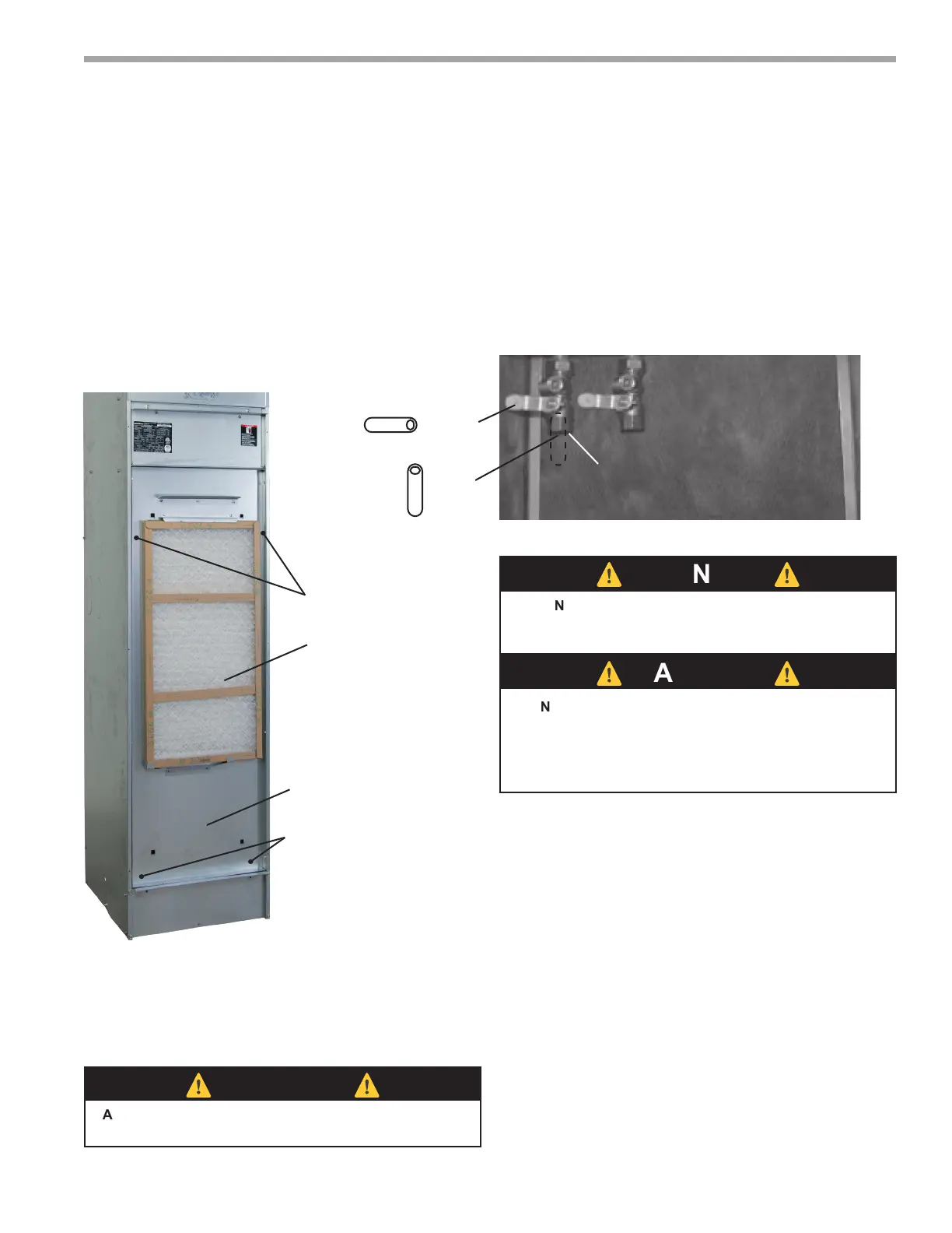
Step 1: Remove lter and inner panel. (Figure 19) For
chassis shipped in cabinet – Remove and discard 4
shipping bolts.
Filter
Shipping Bolt
Location
Shipping
Bolt
Location
Inner Panel
Figure 19
⚠
CAUTION!
⚠
CAUTION! If the risers are under pressure, do not open shut
o valves until installation is complete!
Step 2: Attach the Flex Hoses to shutoffs in the cabinet.
Unpack and examine hose kit. Remove all shipping and/or
packing material such as rubber bands, plastic caps, and
styrofoam. Hose kit should contain (2) hoses.
Figure 20
Cabinet (Style 2 riser back left) Shutoff Location Shown
Supply
(water in)
Return
(water out)
Closed
Position
Open
Position
⚠
WARNING!
⚠
WARNING! Under no circumstances should any part of the
hose itself be gripped or twisted by hand, pliers, channel
locks or any other tool. Leakage or bursting may occur!
Wrenches are used on pipe threads only. Hand tighten swivel
connections.
⚠
WARNING!
⚠
WARNING! Do Not Remove Valve or loosen valve union nut
without rst draining the risers below cabinet level. Check
with contractor if risers have water.
For AHH Hoses - Locate the 2 shutoff valves inside
the unit cabinet (Figure 20). Supply (water in) is always
closest to corner). Attach the hoses to the water valves
with 2 crescent wrenches. Always use a back-up wrench
when tightening the hoses to the shutoff valve. Check
union valve is tight.
For AHU Hose - Locate the 2 shutoff valves inside the
unit cabinet (Figure 20). Supply (water in) is always clos-
est to corner). Check to see if swivel ends have washer
inside them (gure 21). Attach the hoses to the water
valves.
Note: Make sure the valve handles are in a position that
enables them to be fully opened and closed.



 To Next Page