CLIMATEMASTER WATER-SOURCE HEAT PUMPS
TSM/TSL Vertical Stack
Rev.: January 18, 2021
ClimateMaster Water-Source Heat Pumps
68
Unit Start-Up Procedures
Note: All Pre-Installation, Installation, Unit and System
Checkout steps must be followed and completed before
starting unit. Startup sequence and number of steps may
change for your installation. Follow all safety precautions.
Fill out startup log sheet(in this manual) as steps are
completed. Must be certied licensed service technician
to perform startup and troubleshooting.
If operation in any mode has excessive noise or vibration,
stop and correct. Check and repair any water leakage.
1. Adjust all valves to their full open positions. Turn on
the line power to all heat pumps.
2. Turn the thermostat fan position to FAN ON. Blower
should start. Verify all speeds function.
3. Balance air ow at registers.
4. Room temperature should be within the minimum-
maximum ranges of Tables 11 & 12. During start-up
checks, loop water temperature entering the heat
pump should be between 60°F [16°C] and 95°F
[35°C]
5. Set thermostat to off position
6. Remove return air panel and open chassis control box.
a. Turn on power, measure incoming high voltage at
Compressor Contactor (CC), measure low voltage at
board R and C.
b. Amp clamp black wire from CC1 T1.
c. Connect temperature thermocouples to entering and
leaving water lines at the chassis. Note for units with
DXM2- EWT, LWT, LAT, discharge line, LT1, and LT2
temperatures can be read with service tool or at com-
municating thermostat
7. Inner panel and lter must be on chassis to block air
from bypassing air coil. Bypass air will cause unit to
fault off.
8. Check cooling mode (Reversing valve energized)
a. Set thermostat to cool and set temperature for
5 degrees lower than room temperature. It may
take up to 5 minutes for compressor to start.
Test mode will reduce safety time delay. Run 5
minutes minimum after compressor starts before
taking data.
b. Air leaving should be 10 to 25°F (5.5 and 14°C)
lower than entering air. Check air coil, if humidity
is over 50% coil face should be damp but not
icing up.
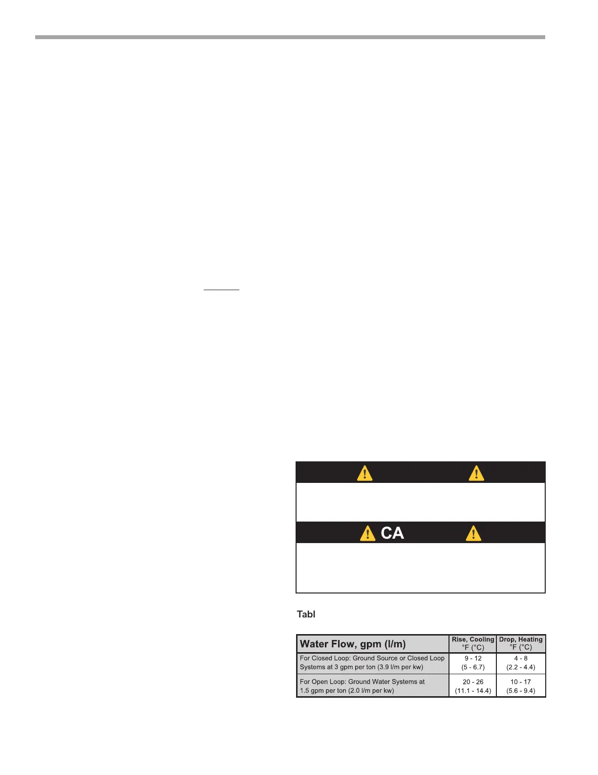
c. Water temperature leaving should be higher than
entering, see Water temperature change table.
9. Check heating mode
a. Set thermostat to heat and set temperature for
5 degrees higher than room temperature. It may
take up to 5 minutes for compressor to start.
Test mode will reduce safety time delay. Run 5
minutes minimum after compressor starts before
taking data.
b. Air leaving should be 20 to 30F (11 and 17 C)
higher than entering air.
c. Water temperature leaving should be lower than
entering, see Water temperature change table.
10. When testing is completed
a. set thermostat to owners instructions.
b. Re assemble all parts.
11. Save start up log sheet for future reference.
12. BE CERTAIN TO FILL OUT AND FORWARD
ALL WARRANTY REGISTRATION PAPERS TO
CLIMATEMASTER.
Note: If performance during any mode appears
abnormal, refer to the CXM and DXM2 sections or
troubleshooting section of this manual. To obtain
maximum performance, the air coil should be cleaned
before start-up. A 10% solution of dishwasher
detergent and water is recommended.
WARNING! When the disconnect switch is closed, high
voltage is present in some areas of the electrical panel.
Exercise caution when working with energized equipment.
CAUTION! Verify that ALL water control valves are open and
allow water ow prior to engaging the compressor. Freezing
of the coax or water lines can permanently damage the heat
pump.
⚠
WARNING!
⚠
⚠
CAUTION!
⚠
This is used in the TRW IOM-option for open loop is deleted
Table 13: Water Temperature Change
Through Heat Exchanger



 To Next Page