CLIMATEMASTER WATER-SOURCE HEAT PUMPS
TSM/TSL Vertical Stack
Rev.: January 18, 2021
ClimateMaster Water-Source Heat Pumps
60
Start-Up Preparation
System Cleaning and Flushing - Cleaning and ushing
the unit is the single most important step to ensure
proper start-up and continued efcient operation of
the system. Follow the instructions below to properly
clean and ush the system: Do not ush through TSM
chassis. Coax can get plugged and water ow will be
reduced, causing poor performance and may cause LT1
sensor to trip.
1. Verify that electrical power to the unit is disconnected.
2. Verify that supply and return riser service valves are
closed at each unit.
3. Fill the system with water. Bleed all air from the
system but do not allow the system to over ow.
Check the system for leaks and make any required
repairs.
4. Adjust the water and air level in the expansion tank.
5. With strainers in place, (ClimateMaster recommends
a strainer with a #20 stainless steel wire mesh) start
the pumps. Systematically check that all of the air is
bled from the system.
6. Verify that make-up water is available and adjusted to
properly replace any space remaining when all air is
evacuated. Check the system for leaks and make any
additional repairs required.
7. Set the boiler to raise the loop temperature to
approximately 85°F [29.4°C]. Open the drain at the
lowest point in the system. Verify that make-up water
replacement rate equals rate of bleed. Continue to
bleed the system until the water appears clean or for
at least three hours whichever is longer.
8. Completely drain the system.
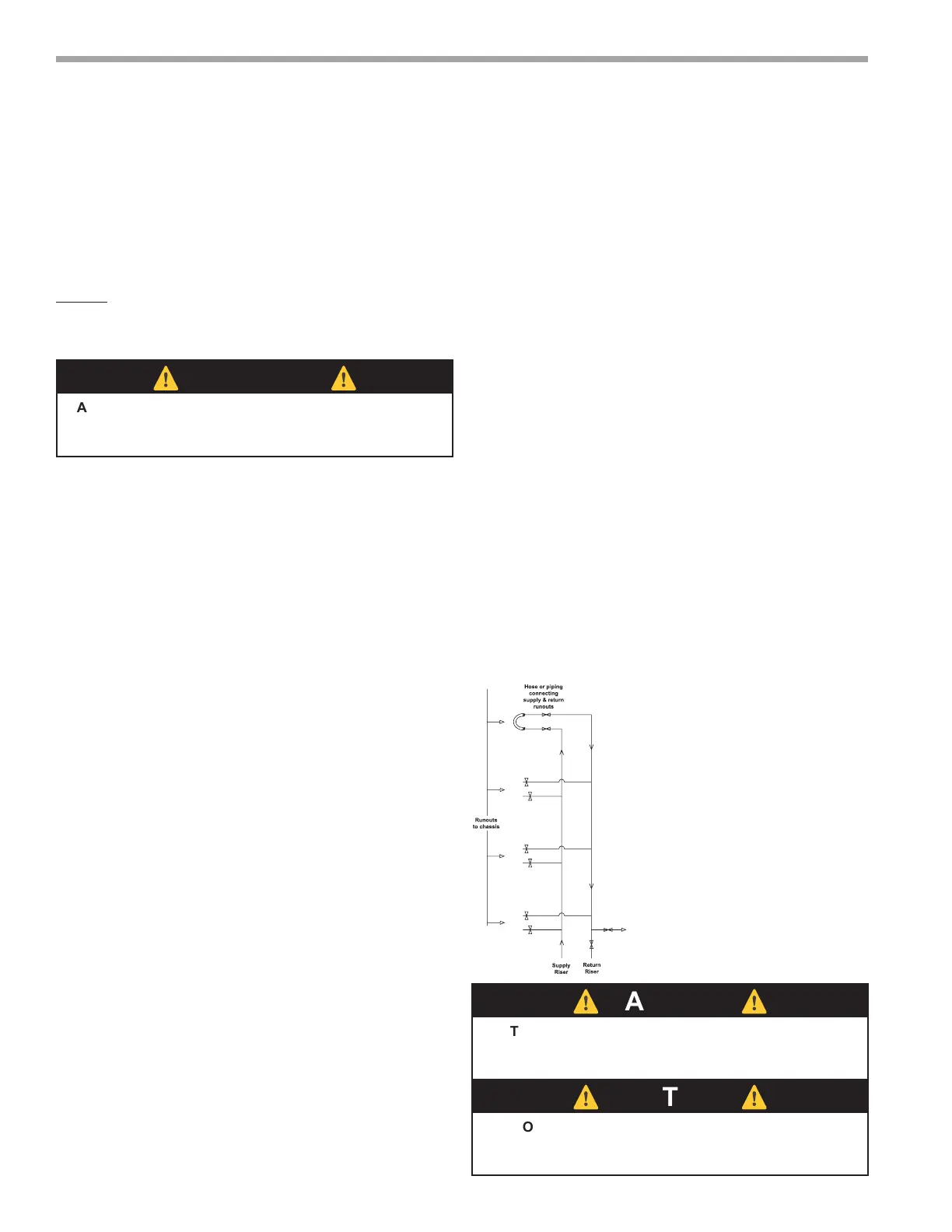
Flush risers as follows: (Refer to Figure 24).
1. Remove cabinet lter and front inner panel. Save
these for re-installation after the chassis is installed.
2. Close shut-off valves at each cabinet on the riser
except the shut-off valve on the top oor.
3. At the top oor, install the hose kit and connect the
ends of the hoses with the factory riser ush adapter
from AFL5751. For sweat shutoffs, one AHU hose
can be used.
4. Flush solution through supply riser. Note: The solution
passes through the top oor connection down the
return riser.
5. When the building has more than 10 oors, connect the
supply and return runouts on the top two oors to divide
the water ow and reduce pressure drop at the pump.
To
Waste
Figure 24: Typical piping arrangement for ushing risers.
⚠
WARNING!
⚠
WARNING! To prevent injury or death due to electrical shock
or contact with moving part, open unit disconnect before
servicing unit.
⚠
CAUTION!
⚠
CAUTION! Do Not use "Stop-Leak" or any similar chemical
agent in this system. Addition of these chemicals to the loop
water can foul the system and can inhibit unit operation.
⚠
CAUTION!
⚠
CAUTION! To avoid possible damage to piping systems
constructed of plastic piping, DO NOT allow loop temperature
to exceed 110°F [43.3°C].
6. Repeat ushing procedure for each set of risers in the
building.
7. Rell the system and add in a proportion of trisodium
phosphate approximately one pound per 150 gallons
[0.4kg per 500 liters] of water. Reset the boiler to
raise the loop temperature to about 100°F [37.8°C].
8. Circulate the solution for between 8 to 24 hours. At
the end of this period, shut off the circulating pump
and drain the solution. Repeat system cleaning if
desired.
9. Open the supply and return riser service valves at
each unit. Rell the system and bleed off all air.
10. Units with internal pumps, to prevent cavitation and
pump failure, air must be bleed from both sides of
pump. First close off supply and open return shutoff.
Open air bleed downstream of pump, bleed air, next
close return and open supply shutoff, bleed air. Close
air bleed.
11. Test the system pH with litmus paper. The system
water should have a pH of 6 to 8.5. Add chemicals as
appropriate to maintain pH levels.
12. When the system is successfully cleaned, ushed,
relled, and bled, check the main system panels,
safety cutouts, and alarms. Set controls to properly
maintain loop temperature.



 To Next Page