CLIMATEMASTER WATER-SOURCE HEAT PUMPS
Tranquility
®
20 (TS) Series
Rev.: June 5, 2020
ClimateMaster Water-Source Heat Pumps
28
Electrical – Low Voltage Wiring
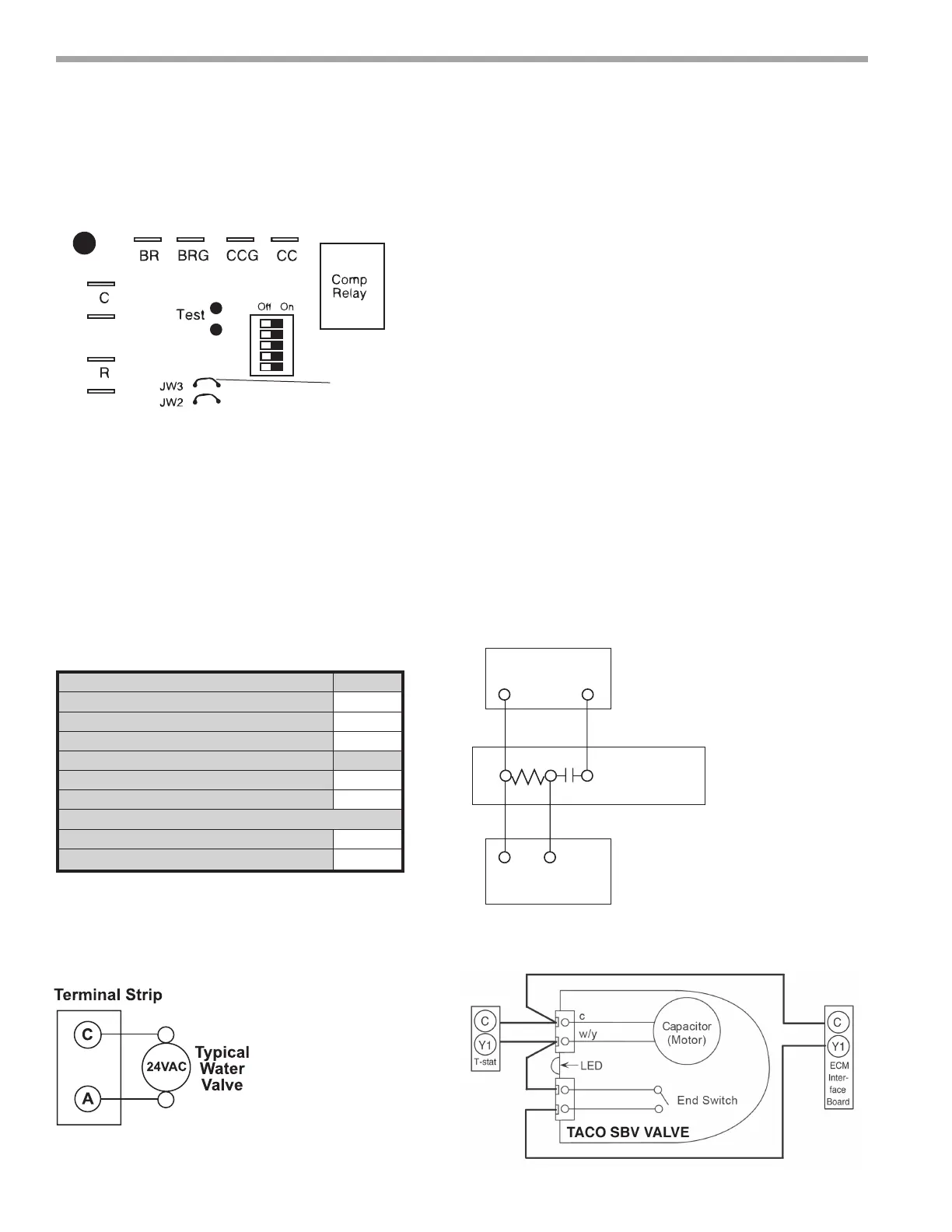
Figure 18: LT1 Limit Setting
CXM PCB
LT1
LT2
JW3-LT1 jumper
should be
clipped for low
temperature
operation
Accessory Connections
A terminal paralleling the compressor contactor coil has
been provided on the CXM/DXM2 control. Terminal “A”
is designed to control accessory devices, such as water
valves. Note: This terminal should be used only with 24
Volt signals and not line voltage. Terminal “A” is energized
with the compressor contactor. See Figure 19 or the
specic unit wiring diagram for details.
Figure 19: Accessory Wiring
Low Voltage VA Ratings
Component VA
Typical Blower Relay 6 - 7
Typical Reversing Valve Solenoid 4 - 6
30A Compressor Contactor 6 - 9
Subtotal 16 - 22
+ CXM board (5 - 9 VA)* 21 - 31
Remaing VA for Accessories 19 - 29
+ DXM2 board (8 - 12 VA)* 24 - 34
Remaing VA for Accessories 41 - 51
*Standard transformer for CXM board is 50VA.
Optional DXM2 board and/or DDC controls
include 75VA transformer.
Figure 20: AVM Valve Wiring
Figure 21: Taco SBV Valve Wiring
Y
1
2
3
Y
AVM
Taco Válvula
Calentador Interruptor
Unidad Empacada
C
C
Aquastat
Y1
1
2
3
Y1
AVM
Taco Valve
Heater Switch
DXM2
Water Solenoid Valves - An external solenoid valve(s)
should be used on ground water installations to shut off
ow to the unit when the compressor is not operating. A
slow closing valve may be required to help reduce water
hammer. Figure 19 shows typical wiring for a 24VAC
external solenoid valve. Figures 20 and 21 illustrate
typical slow closing water control valve wiring for Taco
500 series (ClimateMaster P/N AVM) and Taco SBV
series valves. Slow closing valves take approximately
60 seconds to open (very little water will ow before
45 seconds). Once fully open, an end switch allows the
compressor to be energized. Only relay or triac based
electronic thermostats should be used with slow closing
valves. When wired as shown, the slow closing valve will
operate properly with the following notations:
1. The valve will remain open during a unit lockout.
2. The valve will draw approximately 25-35 VA through
the “Y” signal of the thermostat.
Note: This valve can overheat the anticipator of an
electromechanical thermostat. Therefore, only relay or
triac based thermostats should be used.