climatemaster.com
29
Tranquility
®
20 (TE) Series
Rev.: June 5, 2020
THE SMART SOLUTION FOR ENERGY EFFICIENCY
Electrical –Thermostat Wiring
ATM11C11 Thermostat
ATM11C11 Thermostat
Connection to CXM Control
Connection to DXM2 Control
Compressor
Reversing Valve
Fan
24Vac Hot
Y
W
O
G
R
Y
O
G
R
CXM
Compressor
Reversing Valve
Fan
24Vac Hot
DXM2
Y1
O/W2
G
R
Y
W
O
G
R
Thermostat Installation - The thermostat should be
located on an interior wall in a larger room, away from
supply duct drafts. DO NOT locate the thermostat in areas
subject to sunlight, drafts or on external walls. The wire
access hole behind the thermostat may in certain cases
need to be sealed to prevent erroneous temperature
measurement. Position the thermostat back plate against
the wall so that it appears level and so the thermostat
wires protrude through the middle of the back plate. Mark
the position of the back plate mounting holes and drill
holes with a 3/16” (5mm) bit. Install supplied anchors
and secure plate to the wall. Thermostat wire must be 18
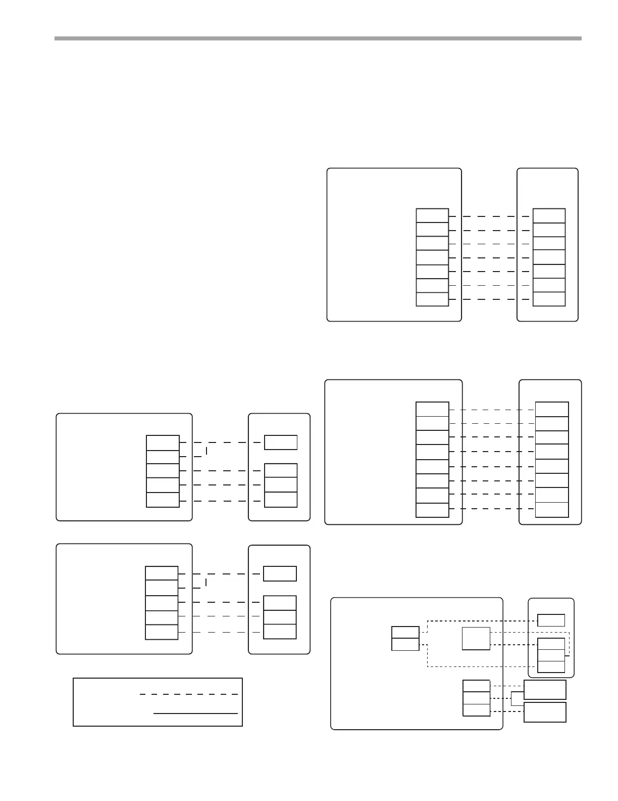
AWG wire. Representative thermostat wiring is shown in
Figures 22a-d however, actual wiring connections should
be determined from the thermostat IOM and or unit wiring
diagram. Practically any heat pump thermostat will work
with ClimateMaster units, provided it has the correct
number of heating and cooling stages.
Figure 22a: Units With PSC Fan
Figure 22c: Units with ClimaDry
®
Reheat
ATP32U04 Thermostat
Connection to DXM2 Control (PSC Fan)
Connection to DXM2 Control
Compressor
Dehumidification
Reversing Valve
Fan
24Vac Hot
24Vac Common
Fault LED
Electric Heat
Y1
DH
O
G
R
C
L
W1
Y1
H
O/W2
G
R
C
AL1
W
DXM2
P1
Compressor
Compressor Stage 2
Reversing Valve
Fan
24Vac Hot
24Vac Common
Fault LED
DXM2
Y1
Y2
H
O/W2
G
R
C
AL1
W
Y1
Y2
DH
O
G
R
C
L
W1
Two-stage unit with ClimaDry Modulating
Reheat Option and DXM board
Single stage unit with ClimaDry Modulating Reheat Option and PSC fan
Figure 22b: Units With ECM Fan
ATP32U03 Thermostat
Connection to ECM Control
Compressor
Heating Stage 2
Reversing Valve
Fan
24Vac Hot
24Vac Common
Fault LED
Y1
Y2
O
G
R
C
L
Y
Y2
O
G
R
C
AL1
ECM
Interface
Board
Field Wiring
Factory Wiring
Figure 22d: Communicating Thermostat Connection to
DXM2 Control
Thermostat
Connection to DXM2 Control
Compressor
Compressor Stage 2
Reversing Valve
Fan
24Vac Hot
24Vac Common
Fault LED
DXM2
Board
Y1
Y2
W
H
O
G
R
C
AL1
Y1
Y2
W
DH
O
G
R
C
L
iGate
®
Thermostat
ATC
32U03C
Figure 24a: Communicating Thermostat
24Vac Hot
DXM2
24V
Dehumidification
Notes:
Auxiliary Heat
1) ECM automatic dehumidification mode operates with dehumidification airflows
in the cooling mode when the dehumidification output from thermostat is active.
Normal heating and cooling airflows are not affected.
2) DXM2 board DIP switch S2-7 must be in the auto dehumidification mode for
automatic dehumidification.
3) DH connection not possible with units with internal variable speed pump. Use ATC32U03C.
4) Only use ATC Communicating Thermostat when using Humidifier (H Input) in
units with internal variable speed pump.
Figure 24b: Conventional 3 Heat / 2 Cool Thermostat
Connection to DXM2 Control
Comm +
A+
Comm -
B-
B-
OD
ID
GND
Outdoor
Sensor
(Optional)
Remote Indoor
Sensor
(Optional)
24Vac Common
Gnd
R
C
A+