climatemaster.com
33
Tranquility
®
20 (TE) Series
Rev.: June 5, 2020
THE SMART SOLUTION FOR ENERGY EFFICIENCY
ECM Blower Control
The ECM fan is controlled by an interface board that
converts thermostat inputs and eld selectable CFM
settings to signals used by the ECM motor controller. Fan
speeds are selected with DIP switch settings. To take
full advantage of the ECM motor features, a multi-stage
thermostat should be used (2-stage heat/2-stage cool or
3-stage heat/2-stage cool).
Note: Power must be off to the unit for at least three
seconds before the ECM motor will recognize a speed
change. The motor will recognize a change in the CFM
Adjust or dehumidication mode settings while the
unit is powered.
There are four different airow settings from lowest
airow rate (speed tap 1) to the highest airow rate
(speed tap 4).
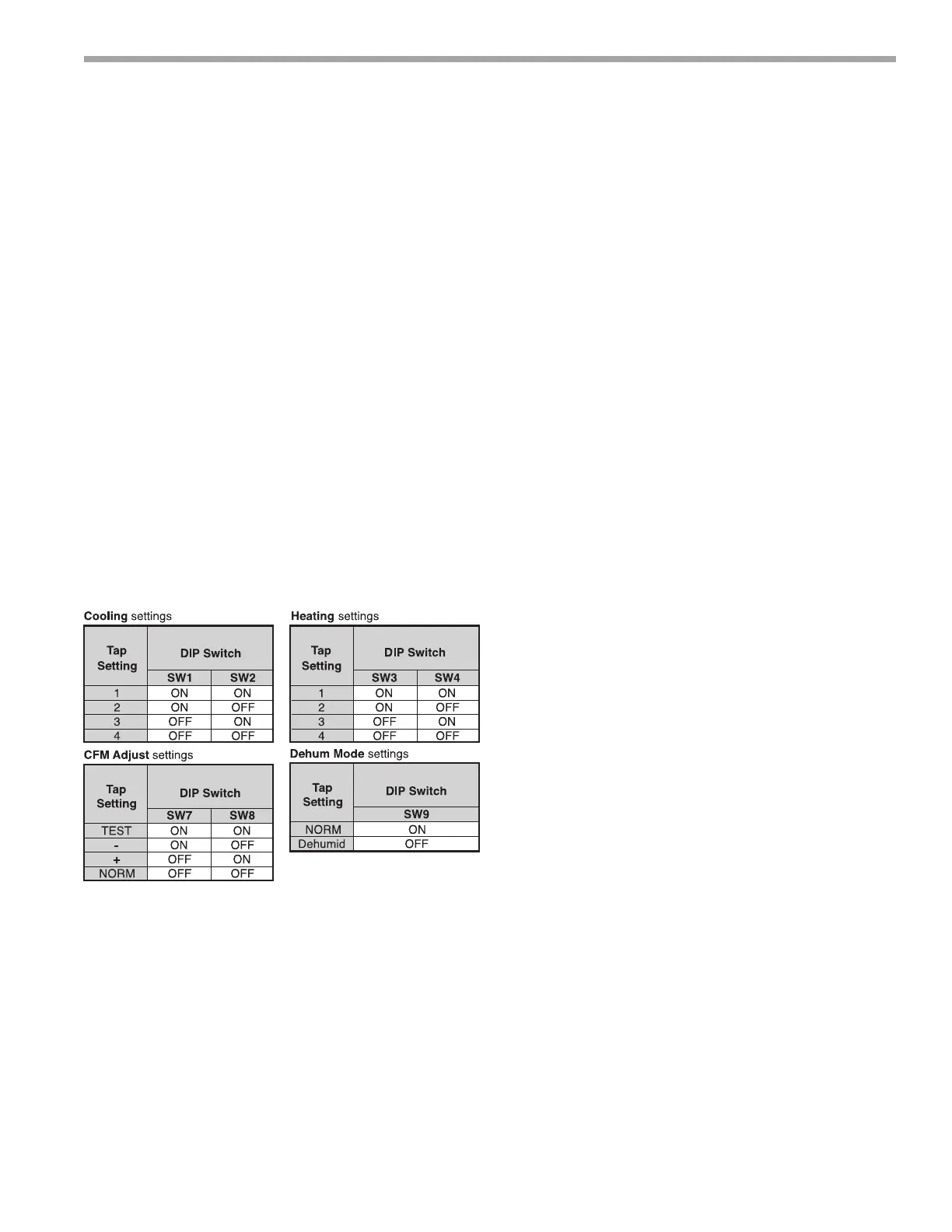
The charts below indicate settings for of the ECM
interface board, followed by detailed information for each
setting.
Cooling Settings: The cooling setting determines the
cooling (normal) CFM for all units with ECM motor.
Cooling (normal) setting is used when the unit is not in
dehumidication mode. Tap 1 is the lowest CFM setting,
while tap 4 is the highest CFM setting. To avoid air coil
freeze-up, tap 1 may not be used if the dehumidication
mode is selected. Consult submittal data or specications
catalog for the specic unit series and model to correlate
speed tap setting to airow in CFM.
Heating Settings: The heating setting determines the
heating CFM. Tap 1 is the lowest CFM setting, while
tap 4 is the highest CFM setting. Consult submittal data
or specications catalog for the specic unit series and
model to correlate speed tap setting to airow in CFM.
CFM Adjust Settings: The CFM adjust setting allows
four selections. The NORM setting is the factory default
position. The + or – settings adjust the airow by +/-
5%. The +/- settings are used to “ne tune” airow
adjustments. The TEST setting runs the ECM motor at
400 CFM/ton, example 2-ton = 800 CFM.
Dehumidication Mode Settings: The dehumidication
mode setting provides eld selection of humidity control.
When operating in the normal mode, the cooling airow
settings are determined by the cooling tap setting above.
When dehumidication is enabled there is a reduction
in airow in cooling to increase the moisture removal of
the heat pump. Consult submittal data or specications
catalog for the specic unit series and model to correlate
speed tap to airow in CFM. The dehumidication mode
can be enabled in two ways.
1. Constant Dehumidication Mode: When the
dehumidication mode is selected (via DIP switch or
jumper setting), the ECM motor will operatewith a
multiplier applied to the cooling CFM settings (approx.
20-25% lower airow). Any time the unit is running in
the cooling mode, it will operate at the lower airow
to improve latent capacity. The “DEHUM” LED will be
illuminated at all times. Heating airow is not affected
Note: Do not select dehumidication mode if cooling
setting is tap 1.
2. Automatic (Humidistat-controlled)
Dehumidication Mode: When the dehumidication
mode is selected (via DIP switch) AND a humidistat
is connected to terminal DH), the cooling airow
will only be reduced when the humidistat senses
that additional dehumidication is required. The DH
terminal is reverse logic. Therefore, a humidistat (not
dehumidistat) is required. The “DEHUM” LED will
be illuminated only when the humidistat is calling
for dehumidication mode. Heating airow is not
affected. Note: Do not select dehumidication mode
if cooling setting is tap 1.