climatemaster.com
29
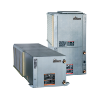
Tranquility
®
22
(
TY
)
Series
Rev.: July 8, 2021
THE SMART SOLUTION FOR ENERGY EFFICIENCY
DXM2 Controls
DXM2 Control - For detailed control information, see
DXM2 Application, Operation and Maintenance (AOM)
manual (part # 97B0003N15).
Field Selectable Inputs - Test mode: Test mode allows
the service technician to check the operation of the
control in a timely manner. By momentarily pressing the
TEST pushbutton, the DXM2 control enters a 20 minute
test mode period in which all time delays are sped up
15 times. Upon entering test mode, the status LED
display will change, either ashing rapidly to indicate
the control is in the test mode, or displaying a numeric
ash code representing the current airow if an ECM
blower is connected and operating. For diagnostic ease at
conventional thermostats, the alarm relay will also cycle
during test mode. The alarm relay will cycle on and off
similar to the fault LED to indicate a code representing the
last fault, at the thermostat. Test mode can be exited by
pressing the TEST pushbutton for 3 seconds.
Retry Mode – If the control is attempting a retry of a fault,
the fault LED will slow ash (slow ash = one ash every
2 seconds) to indicate the control is in the process of
retrying.
Field Conguration Options – Note: In the following eld
conguration options, jumper wires should be clipped
ONLY when power is removed from the DXM2 control.
Water coil low temperature limit setting: Jumper 3 (JW3-
LT1 Low Temp) provides eld selection of temperature
limit setting for LT1 of 30°F or 10°F [-1°F or -12°C]
(refrigerant temperature).
Not Clipped = 30°F [-1°C]. Clipped = 10°F [-12°C].
Alarm relay setting: Jumper 1 (JW1-AL2 Dry) provides
eld selection of the alarm relay terminal AL2 to be
jumpered to 24VAC or to be a dry contact (no connection).
Not Clipped = AL2 connected to R. Clipped = AL2 dry
contact (no connection).
DIP Switches – Note: In the following eld conguration
options, DIP switches should only be changed when
power is removed from the DXM2 control.
DIP Package #1 (S1) – DIP Package #1 has 8 switches
and provides the following setup selections:
1.1 - Unit Performance Sentinel (UPS) disable: DIP Switch
1.1 provides eld selection to disable the UPS feature.
On = Enabled. Off = Disabled.
1.2 - Compressor relay staging operation: DIP 1.2
provides selection of compressor relay staging operation.
The compressor relay can be selected to turn on with a
stage 1 or stage 2 call from the thermostat. This is used
with dual stage units (2 compressors where 2 DXM2
controls are being used) or with master/slave applications.
In master/slave applications, each compressor and fan will
stage according to its appropriate DIP 1.2 setting. If set
to stage 2, the compressor will have a 3 second on-delay
before energizing during a Stage 2 demand. Also, if set for
stage 2, the alarm relay will NOT cycle during test mode.
On = Stage 1. Off = Stage 2.
1.3 - Thermostat type (heat pump or heat/cool): DIP 1.3
provides selection of thermostat type. Heat pump or
heat/cool thermostats can be selected. When in heat/
cool mode, Y1 is the input call for cooling stage 1; Y2 is
the input call for cooling stage 2; W1 is the input call for
heating stage 1; and O/W2 is the input call for heating
stage 2. In heat pump mode, Y1 is the input call for
compressor stage 1; Y2 is the input call for compressor
stage 2; W1 is the input call for heating stage 3 or
emergency heat; and O/W2 is the input call for reversing
valve (heating or cooling, depending upon DIP 1.4).
On = Heat Pump. Off = Heat/Cool.
1.4 - Thermostat type (O/B): DIP 1.4 provides selection of
thermostat type for reversing valve activation. Heat pump
thermostats with “O” output (reversing valve energized
for cooling) or “B” output (reversing valve energized for
heating) can be selected with DIP 1.4.
On = HP stat with “O” output for cooling. Off = HP stat
with “B” output for heating.
1.5 - Dehumidication mode: DIP 1.5 provides selection of
normal or dehumidication fan mode. In dehumidication
mode, the fan speed relay will remain off during cooling
stage 2. In normal mode, the fan speed relay will turn on
during cooling stage 2.
On = Normal fan mode. Off = Dehumidication mode.
1.6 – DDC output at EH2: DIP 1.6 provides selection for
DDC operation. If set to “DDC Output at EH2,” the EH2
terminal will continuously output the last fault code of
the controller. If set to “EH2 normal,” EH2 will operate as
standard electric heat output.
On = EH2 Normal. Off = DDC Output at EH2.
1.7– Boilerless operation: DIP 1.7 provides selection of
boilerless operation. In boilerless mode, the compressor is
only used for heating when LT1 is above the temperature
specied by the setting of DIP 1.8. Below DIP 1.8 setting,
 Loading...