P/N: 57017, Rev. 3 Page 23
8. Center the bar by evenly adjusting the jacking screws then tighten the hex-head
cap screws.
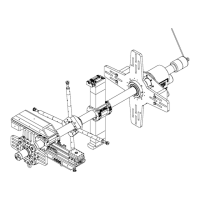
9. Slide the bar and bearing support into the work piece.
10. Using a dial indicator and the jacking screws, center the bar inside the work
piece. Tighten the jacking screw against the inside of the bore. Do not exceed 22
ft-lbs (30 Nm) of torque.
11. If mounting the RDU between the bearing supports, do so now. See Section 3.6
on page 24 for instructions.
12. If mounting another ID-mount bearing, repeat the above steps.
3.4.1 If mounting an end-mount bearing
Do the following to set up an end-mount bearing support assembly:
1. Re-check the bar for center by sweeping a dial indicator inside the bore.
2. Adjust the jacking screws, if necessary.
CAUTION
Bearings placed too far apart allow the bar to deform, reducing
bore precision. To keep the bar from deflecting, do not space the
bearing supports more than 5 feet (1.5 m) apart.
3.4.2 Clamping the bearing assembly to the bar
Do the following to clamp the bearing assembly to the bar:
1. Remove the screws holding the lock plate.
2. Slide the lock plate away from the lock nut.
3. Rotate the lock nut using both hands until it is snug. This is the zero reference
point.
4. Mark or note the angular position of the lock nut.
5. Use the offset spanner wrench in the tool kit to rotate the lock nut approximately
1.25—1.5 additional turns.
6. Reapply the lock plate. If necessary, additionally tighten the lock nut until a slot
in the lock plate is aligned with the retaining screw holes.
7. Reinstall the retaining screws.
3.5 Preload bearing kit
The preload bearing kit is only used on bearing assemblies using the bearing
cartridge P/N 23570. It is appropriate in those applications demanding greater
machine stability, especially facing operations. The kit contains a pair of 3.5" (89
mm) hinged clamp collars, one standard and the other with tensioning screws. This
kit can be used in either the vertical or horizontal positions.