B-13
Welding
GLC 353/503/553 MC3
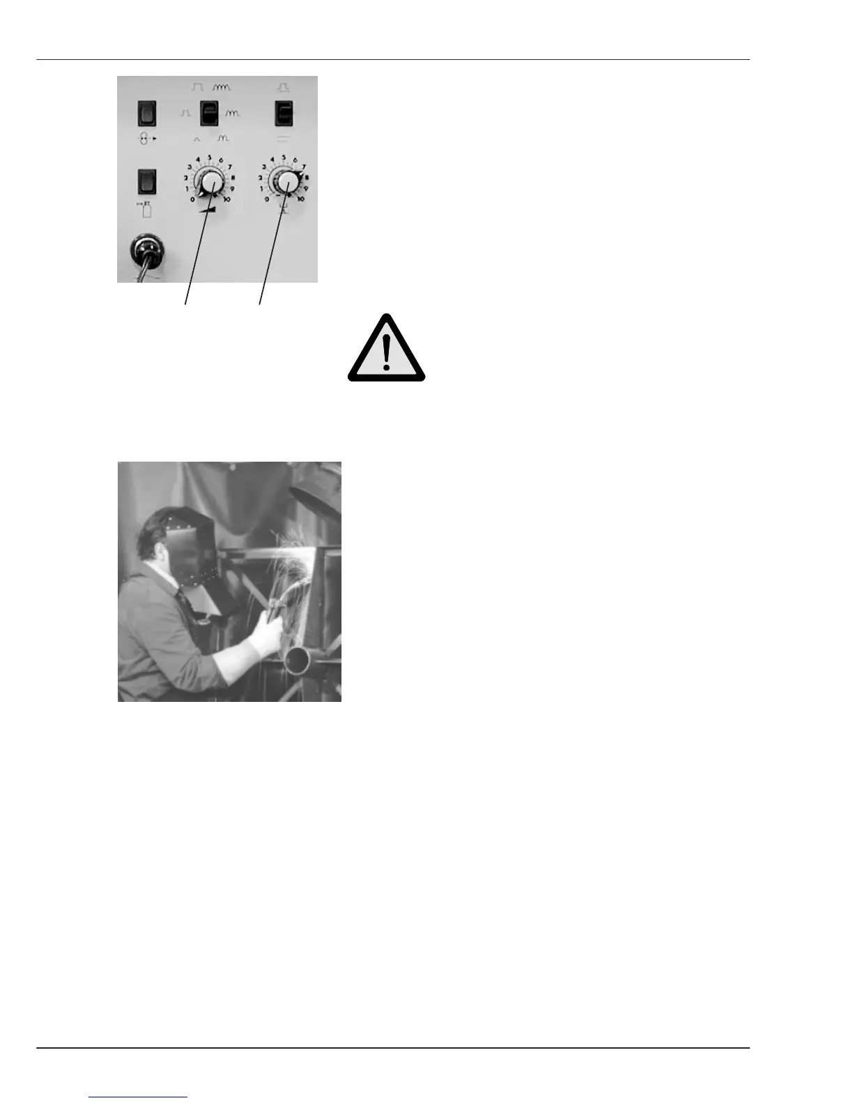
- Select the required Wire feed speed by turning
Potentiometer 1 on the wire drive unit operation panel.
The set value is shown on Display 1 of the power
source.
- Begin welding.
Poti 1 Poti 2 Caution!
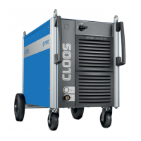
Protect eyes and skin against arc
radiation ! Wear protective clothing !
- Turn Potentiometer 2 to adapt the Weld Voltage
to the set wire feed speed.
- Carry out test welds and optimize the settings
on Potentiometer 1 and 2.
- The actual weld parameters voltage and current
are shown on Display 1 - position Volt and on
Display 2 - position Ampere.
Note: If you select A
Hold
on Display 2, the maximum welding current used during
welding can be read at the end of the welding process.
B2.1 MIG-MAG Normal 2 knob