B-24
Programming
GLC 353/503/553 MC3
P2 Program steps
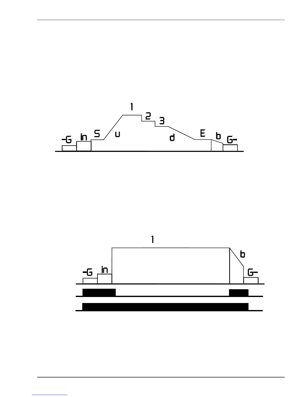
By means of the graphic aid all possible program steps are shown. The abbreviations for the
program steps are shown on display 3. The abbreviations are explained below:
-G Gas preflow 1 Main parameter 1 E End crater program
in Wire "inching-in" speed 2 Main parameter 2 b Burnback
S Start parameter 3 Main parameter 3 G- Gas postflow
u Start ramp (Upslope) d End crater ramp
P3 Operating modes during programming
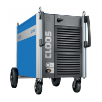
The number of program steps depends on the operating mode. Actuate the torch trigger to
change to the next program step. The following drawings explain the connection (association)
between operating modes, possible program steps and welding torch trigger.
Operating mode: 2 and 4 cycle:
Program steps
4 cycle
2 cycle
Welding torch trigger
The diagram shows the connection between the program steps and the actuation of the torch
trigger as well as the difference between the operating modes 2 cycle and 4 cycle.
P2 Programmschritte