MAN.234 Rev.6 ENG - Use and maintenance manual S19HD page 15 of 126
2.3.1 Frame
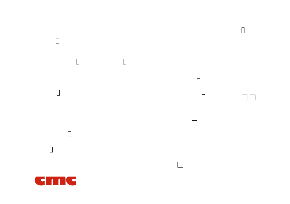
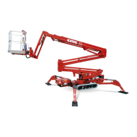
The frame 1 (Picture 3) is a steel structure having a
quality appropriate in order to distribute the weight
of the equipment when the MEWP is in working po-
sition. The frame is equipped with 4 hydraulic jacks
used for stabilisation 2 (Picture 3). The base 3 (Pic-
ture 3) for the support slewing ring is on the frame.
2.3.2 Turret
The turret 4 (Picture 3), made of quality steel, is
fixed to the bearing (slewing ring). The rotation of
the superstructure is allowed by a hydraulic motor
with brake normally closed, constrained to the turret.
2.3.3 Pantograph
The pantograph 5 (Picture 3) is constituted by two
parallel arms (pantograph upper crank and panto-
graph lower crank and by the pantograph connect-
ing rod 6 (Picture 3). The arms (tubular with rectan-
gular section, bended and electro-welded) and the
connecting rod are made with high quality steel
sheets. The movement of the pantograph (lifting and
lowering the pantograph) is obtained thanks to the
hydraulic cylinder for lifting the pantograph 7 (Pic-
ture 3). This cylinder is fastened to the turret (barrel
side) and to the upper pantograph crank (rod side)
and is equipped with double-acing valve.
The pantograph has a working range from 0° to
about +65° with respect to the horizontal.
2.3.4 Telescopic boom
The telescopic boom 8 (Picture 3) is hinged to the
turret. The telescopic boom is composed of three
elements: a fixed boom 9 (Picture 3) hinged to the
connecting rod and two telescopic booms 10 11
(Picture 3).
The extraction movement (or return) of the telescop-
ic boom is obtained by moving the "telescopic boom
extraction cylinder" 12 (Picture 3).
The lifting (or lowering) movement of the telescopic
boom is obtained by moving the "telescopic boom
lifting cylinder" 13 (Picture 3).
2.3.5 Basket
The basket 14 (Picture 3) is connected to the sec-
ond boom of the telescopic element through the