MAN.219 Rev.8 ENG - Use and maintenance manual S19N page 12 of 71
The auxiliary electric engine, if present, can be activated pushing the red
button SB located on electric emergency box (Picture 11) or by turning to
the left the selector MS in the basket control station (Picture 5).
The MEWP can also be equipped with a power supply selector (Picture 4d
- *optional) capable of providing electric motor’s dual power supply at 110
V and 230 V. The desired one can be set thanks to a special electric selec-
tor (Picture 4d - *optional) fixed to the frame.
This allows you to have electrical outlets of both voltages (Picture 4e): on
the ground to power the electric motor and/or in the basket (*optional) to
power work tools. Note that basket’s supply voltage is not settable and is
provided according to customer’s need.
To recharge the batteries (no engine activated):
1. couple the 110/120/230 V socket (power line) to the plug on the
machine and lift the button provided on the machine's magneto-
thermic panel;
2. the batteries will be charging and, if the electric system is on, the
progress of the charging process will be shown by appropriate leds
on the control stations.
When the state of batteries charge, during the use, reaches the
lowest level (under 10%), all work maneuvers will be interrupt-
ed, and it will only be possible to close the machine again.
It is absolutely forbidden to direct high-pressure jets of water
onto the support containing the battery pack. High water pres-
sure could generate serious and irreversible problems in the
operation of the machine.
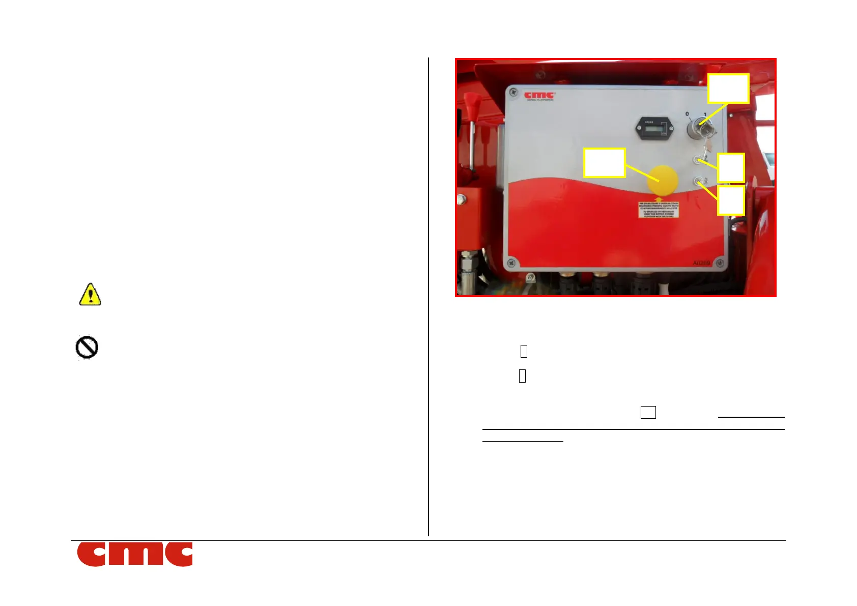
If MEWP in full lithium* version, the removable ignition key SK (Picture 4c)
supplied can be inserted into the proper switching on/off station placed on
the right side of chassis, to turn on the electric system.
Picture 4c: switching on/off station for full lithium* version.
This switching on/off station contains:
• the key lock SK;
• the led 1 (Picture 4b) indicating system power supply: it is on
when the SK key is in position 1;
• the led 2 (Picture 4b) for aerial part use consent: if lighted on, it
allows the maneuvers of the aerial part only when stabilization is
correctly performed;
▪ “dead man” stabilization button DB (Picture 4b): it must be held
pressed together with levers of outriggers control station to stabi-
lize or destabilize.
• the hourmeter.
On the left side of the electric box, there is the platform fuse board.