MAN.219 Rev.8 ENG - Use and maintenance manual S19N page 23 of 71
If these conditions are not met, it is strictly forbidden to use the
MEWP.
4. Be careful not to exceed the maximum slope limits that can be
faced by the machine.
5. Place the MEWP on the chosen area.
6. Mark the working area with proper signs (white-red tape, white-red
chains, pins, etc.).
When traveling, respect a safety distance of at least 4 meters.
4.4.2 MEWP stabilization
The MEWP has only one stabilization area, given by the openings of the
front and rear outriggers. An electronic locking system uniquely ensures
the working area.
The movement of the outriggers must be possible only when the panto-
graph and the boom are resting on their supports. This is signalled by the
lighting up of led 9 on the turret box (Picture 11).
7. Reach the outriggers control station (Picture 7);
8. Using the “outriggers control station”, lower the front and rear out-
riggers with the levers 1, 2, 3, 4 (par. 3.2.2). The release of the
outriggers leads first to the contact of the four outriggers plates
with the ground and then to the lifting of the frame. Proceed with
the complete stabilization of the machine.
The tracks should remain extended to maximum width for improved
stability and increased ground clearance (*optional). Note that both
the width and the height of the MEWP are affected by adjusting
track extension. One track can be adjusted to level the chassis when
travelling over uneven terrain, but travelling across a slope should
be avoided.
It is essential to carry out the stabilization operations by oper-
ating on all four levers simultaneously. Once the feet will all have
touched the ground, it will be possible to continue running short al-
ternate cycles before on the two front stabilizers and then on the two
rear ones.
Verify that the maximum slope to stabilize on an obstacle does
not exceed 6° (11%).
Check that the tracks are completely lifted from the ground.
9. Check the machine levelling, by watching the bubble level L (Pic-
ture 7) located on the chassis: the maximum chassis slope allowed
is 1°.
4.4.3 Access to the basket
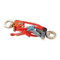
10. To carry out the basket operations, it is necessary to proceed with
the basket assembly after having turned off the machine.
Picture 16: basket coupling.
11. Once the basket is coupled, insert the cotter pin P and the forelock
C (Picture 16).