MAN.243 Rev.5 ENG - Use and maintenance manual S28 page 55 of 138
7. With the pin lifted (Picture 46), rotate the
outrigger taking it in a position which allows
the reinsertion of the same pin. For each
outrigger, it will be possible to choose two
positions (1 or 2): the positions taken by the
outriggers determine the work area.
8. Once reached one of the two outrigger
positions required, push the pin downward
until blocking it.
Check the status of cleanliness and integrity of the
limit switches in-built in the outriggers (cursor,
bracket, spring, etc.) before the operations
described above.
4.4.2.1 Manual stabilization from chassis
control station
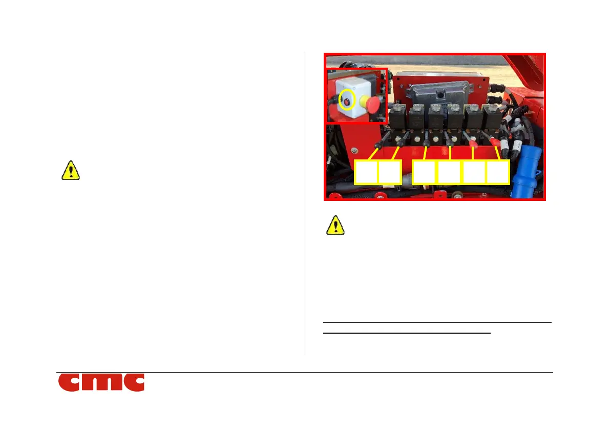
The hydraulic distributor in Picture 47, present on the
frame control station, allows to perform manual
stabilization/destabilization of the machine:
Picture 47: levers of hydraulic distributor.
The tracks should remain extended to maximum
width for improved stability and increased ground
clearance. Note that both the width and the height
of the MEWP are affected by adjusting track
extension. One track can be adjusted to level the
chassis when travelling over uneven terrain, but
travelling across a slope should be avoided.
So, to activate the hydraulic distributor, it is necessary to
keep the red button (dead man) pressed, located at left
side of emergency button (Picture 47), during the levers
handling: