DIGIMINI EMEA/APAC/AUSTRALIA REPEATERS
PRODUCT DESCRIPTION AND USER’S MANUAL
Cobham Wireless – Coverage Date: 11-Oct-15 www.cobham.com/wireless
Document number: 00030UMCD Rev. 5.0
Page |1-5
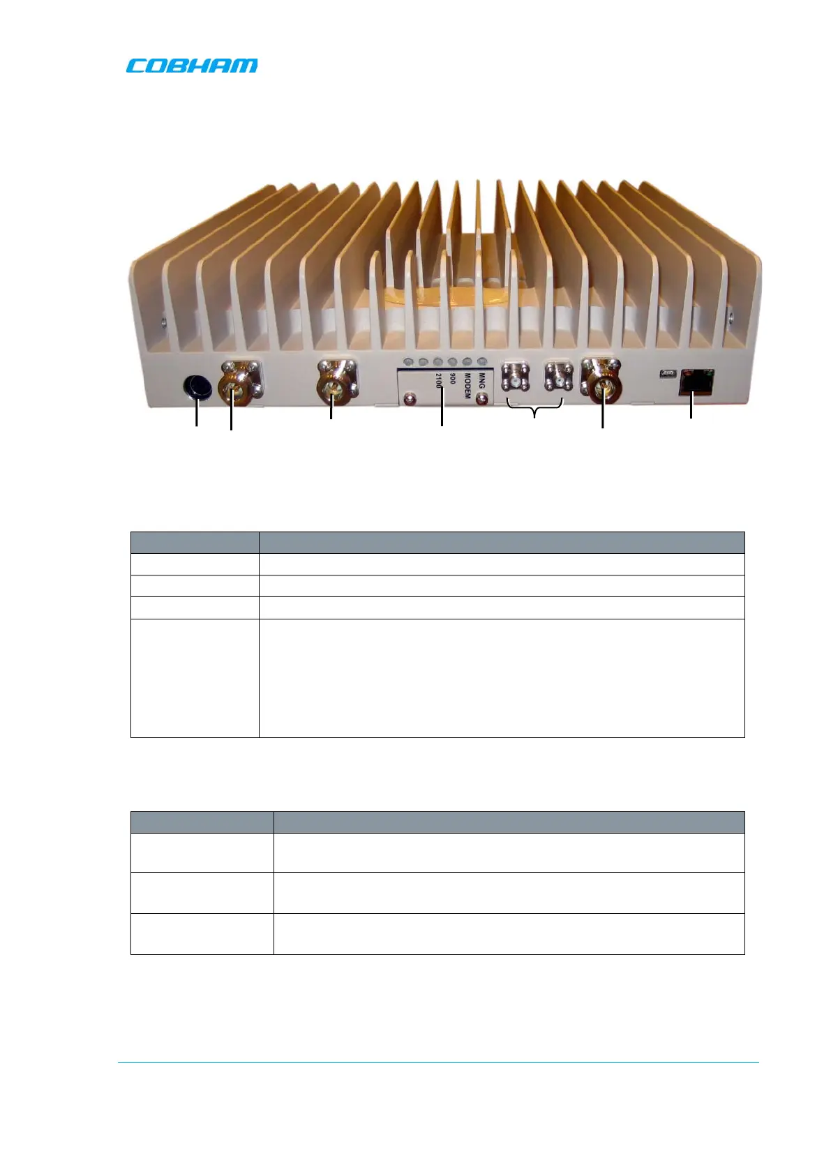
1.7.1 Front Panel Interfaces
The image below shows the unit (the wallmount bracket is not shown).
Figure
1-2: DIGImini Dual-Band Front Panel
The following table provides a description of the front panel connectors.
Port Description
MOBILE Service antenna connections.
BASE Donor antenna connections.
DC Power (12V) Circular, 4-PIN.
RJ 45 Used for setup.
ATTENTION!! Do not connect to the network unless you have purchased
either the DMCU or the external modem support license file.
If the support for external modem License file is acquired, the Ethernet port
can also be connected to the network or used to connect to an external
modem.
*Not in use. Termination is NOT required.
The following table provides a description of the front panel LED indicators (see
6.2.2 for more info).
LED Description
Band specific
LED
(e.g. 850, 1900, etc)
Downlink path status and RSSI indication:
MNG Relevant only if connected to DMCU:
CCD Operation status
MODEM Relevant only if connected to DMCU:
DMCU Modem operation status
Power
Mobile
N/A*
Base
ETH
RJ45