Interfaces of the antenna
98-145510-E Chapter 4: Interfaces 4-8
4.2 Interfaces of the antenna
4.2.1 VSAT air interface
The antenna operates in the Ku-band (10.7 to 14.5 GHz) or the Ka-band (19.2 to 30 GHz).
Service capabilities are determined by the connected VSAT modem.
4.2.2 GNSS air interface
The antenna has a GNSS receiver for positioning input from the Positioning system.
4.2.3 Earth magnetic field interface (electronic compass)
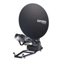
The EXPLORER 8000 series has an electronic compass to support the pointing process.
4.2.4 Connectors on the antenna
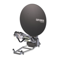
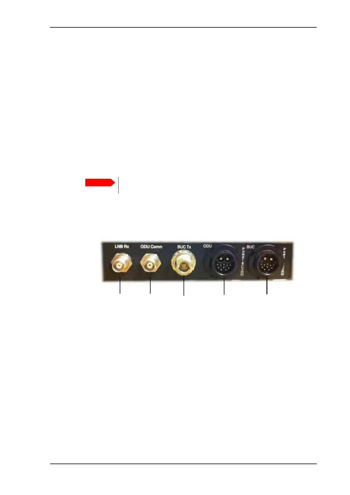
The connectors on the rear of the antenna are located as shown below:
A cable bundle with all necessary cables between antenna and ACU is delivered with the
system. There are 5 connectors on the antenna for connection to the ACU:
• LNB Rx: TNC connector with signal from the LNB to the ACU and power to the LNB
• ODU Comm: TNC connector used for Housekeeping communication between the ACU
and the antenna.
• BUC Tx: N-connector for signal and power from the ACU to the BUC.
• ODU Power & Comm: GTC C4 male connector for antenna power (ODU power) and
information of the antenna to the ACU. For pinout see Connectors for antenna
connection on page 4-3.
• BUC Power & Comm: GTC C4 male connector for power supply to the BUC and for
communication with the BUC. For pinout see Connectors for antenna connection on
page 4-3.
You must calibrate the compass after first installation and every time you
have reinstalled it, see Compass calibration on page 6-19.
Figure 13: Connectors on the rear side of the antenna
LNB Rx ODU Comm ODU Power
& Comm
BUC Tx BUC Power
& Comm
 Loading...