Installation
Sea Tel Tracker 6000
3.
Installation
Thissectioncontainsinstructionsforunpacking,finalassemblyandinstallationoftheequipment.
I
t is highly
recommended that final assembly and installation of the Antenna system be performed by trained
technicians.
Readthiscompletechapterbeforestarting.
NOTE:Thisantennaistobeinstalledinasecured,gated,siteONLY.
3.1.
General Cautions & Warnings
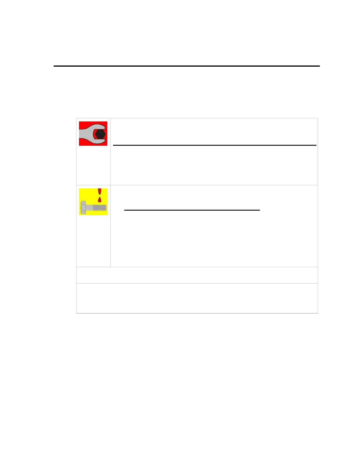
WARNING: Assure that all nut and bolt assemblies are tightened according t o t h e
ti
htenin
t o r q u
value
listed below:
SAE Bolt Size Inch Pounds Metric Bolt Size Kg-cm
1/4-20 75 M6 75.3
5/l6-18
132
M8 150
3/8-16
236
M10 270
1/2-13
517
M12 430
NOTE: All nuts and bolts should be assembled using the appropriate Loctite
thread-locker product number for the thread size of the hardware.
Loctite # Description
222 Low strength for small fasteners.
242 Medium strength
638 High strength for Motor Shafts & Sprockets.
2760 Permanent strength for up to 1” diameter fasteners.
290 Wicking, High strength for fasteners which are already
assembled.
WARNING: Hoisting the sections of the radome with other than a webbed four-part sling may
resul
i
ca t as t ro
hi
cru sh i n
o
th
radome.
CAUTION: The sections of the radome are very light for their size and are subject to large
swaying motions if hoisted under windy conditions. Always ensure that tag lines, attached to the
base o f the radome sections, are attended while the assem bly is being hoisted to its assigned
location.
3.2.
Preparation
Read this entire assembly procedure
before
beginning.
Refer to the System Block diagram, Antenna Schematic, General & and lower level Assembly
drawings, Radome Hole Pattern layout, All Radome Assembly & Installation drawings for your system.
We recommend that you place the crates in the area that you have chosen to assemble each of these
major components. It is recommended that you do not unpack the crates until you are ready to sub-
assemble and install the equipment.
Assure that you have a large, flat, level, open area to sub-assemble the general assembly and the
upper & lower sections of the radome. This area should be clean and free of debris. The site should
also provide protection from wind, rain and other adverse weather.
A hoist, or small crane, is needed to assemble these sub-assemblies to form the final Out Door Unit
(ODU) Assembly.
3‐1
EAR Controlled - ECCN EAR99
 Loading...