Installation
Sea Tel Tracker 6000
3.11.
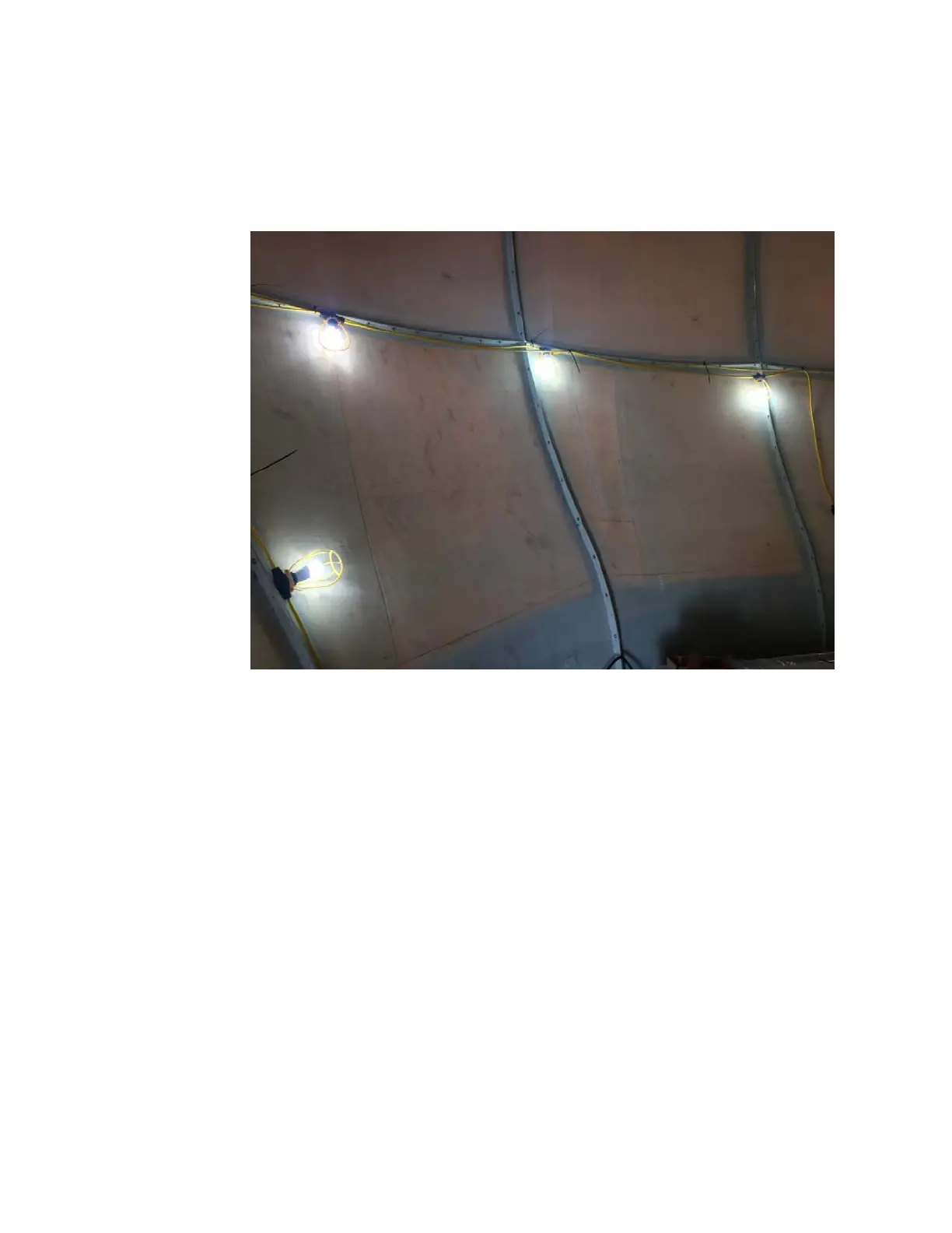
Installing Interior Lighting
Refertodrawings:
92-162776-A1_DMG_RE_M SYSTEM BLOCK DIAGRAM, GLOBALSTAR TRACKER
93-164211-A01 SCHEMATIC, TRACKER 6000 SYSTEM, GLOBALSTAR
62-165842 RADOME LIGHTING KIT, T6000
1. Mount the Light Switch to radome near the radome hatch/door.
2. Route input power to the switch from the AC Power Strip.
3. Route power from the switch to the Power Supply.
4. Provide cover over the power cables to protect them and assure that they are not a trip
hazard.
5. Mount Power Supply in a convenient location based on the length of the interconnecting
cable from the Switch.
6. Mount the splitter in a convenient location based on the locations of the Power Supply and
interconnecting cable.
7. Install the 6 interior lights on inner flanges of the radome, as desired, based on the location
of the Splitter and the interconnecting cables.
8. Mount each light fixture to the inner flange.
9. Use cable ties to route and affix all of the interconnecting cables in place along the flanges.
3.12.
R em ov e the Ser vice Br ack et s
CAUTION; DoNOTremovetheServiceBracketsuntilallassemblyworkhasbeencompletedandyouarereadyto
checkmechanicalrotationoftheantennaorturnantennapowerON.
DANGER:SeveredamagetotheantennaortheassemblypersonnelcanbecausedbyremovingtheService
Bracketsuntilallworkhasbeencompleted.
CAUTION;DoNOTturnantennapowerONuntiltheServiceBracketshavebeenremoved.
3‐19
EAR Controlled - ECCN EAR99
 Loading...