Procedure
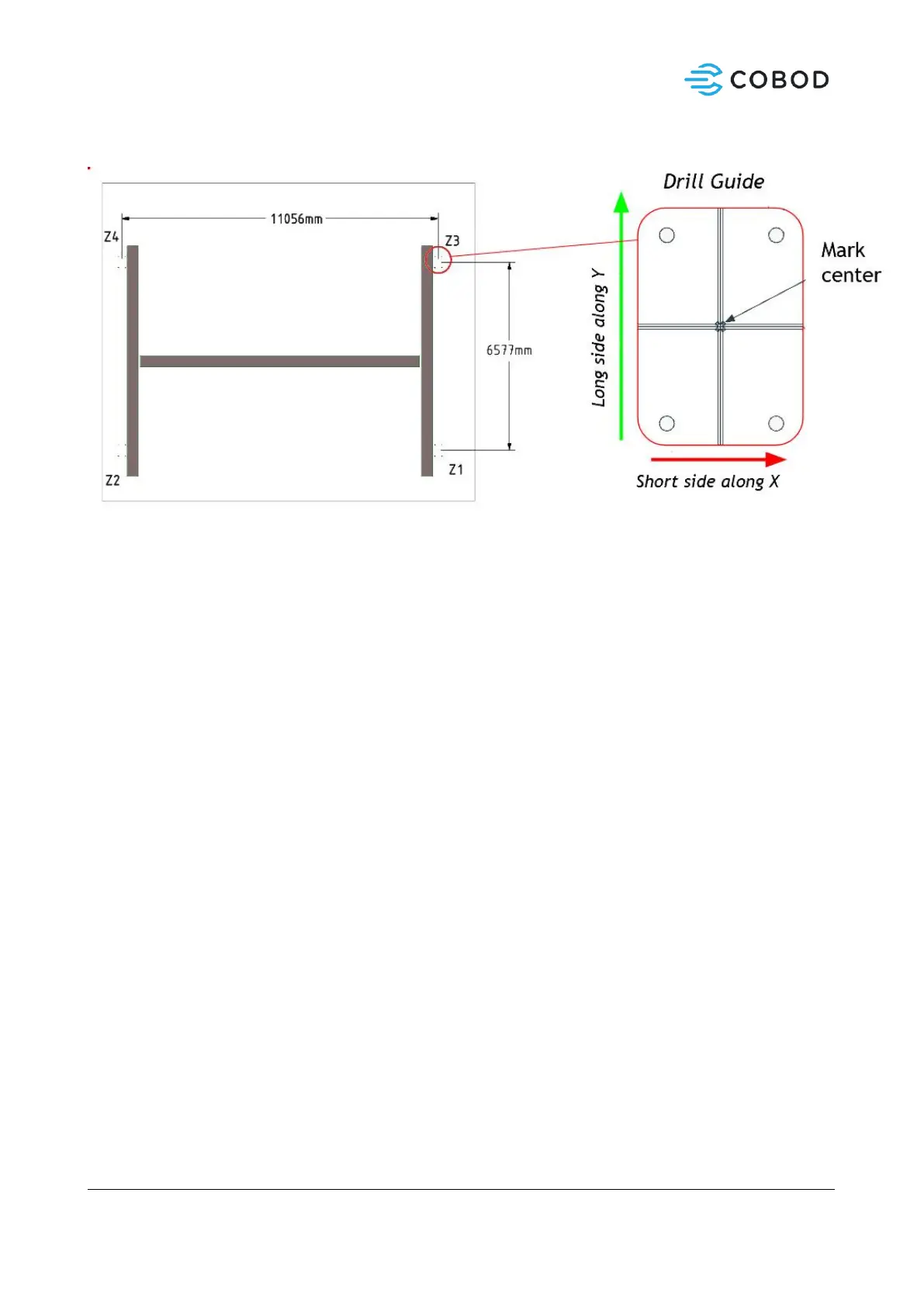
Figure 3: Center distance measures for BOD2
1. Locate first center point (Z1). Mark it.
2. Align marked spot with center hole of the drill guide.
3. Place Angle Laser on drill guide and make sure laser aligns with the grooves.
4. Using drill guide, mark all 4 holes to be clearly visible on the ground surface.
5. Place a small box at Z3 and move until distance and angle is according to Figure 3.
6. Move drill guide to Z3 over the marked point. Verify angle and distance to Z1.
7. Continue counter clockwise until you reach Z2. Measure distance and angle to the starting point.
8. Errors up to 5mm is acceptable and will be adjusted to by later assembly.
9. Drill marked anchor holes with M8 drill. Make sure the holes are vertical.
10. Drill anchor holes with M18 bit to a depth of 145mm.
11. Finally, clear the holes of any debris and dust with compressed air or a dust vacuum cleaner.
12. Using the 2-component glue (Hilti HIT-re 500 V3) fill 4 drilled holes at the time. It should be filled up
to 80%. Follow Hilti instructions for correct and safe use.
13. Insert all 4 anchors, thread side up.
14. Place the drill guide on top, ensuring the anchors are positioned correctly.
15. Carefully remove the drill guide and continue to the next set of holes.
16. Expect to use 1-2 glue cartridges for a full set of 16 holes.
17. Hardening of the glue is temperature dependent. See the curing table to assess how long to wait
before the printer can be installed safely.
 Loading...