X-2 Technical Service Manual 2-1
Publication No: 15-02047
2 Brief Description
This section of the manual provides a brief description of the major
components and circuit functions of the X-2 transceiver as follows:
• Control and switching functions
• Synthesizer operation
• Receive path
• Transmit path
For an in-depth review of these functions refer to Chapter 4 "Technical
Description".
2.1 General
Read this description of the X-2 transceiver with the circuit drawing shown
in Table 2.1.
Title Circuit Diagram
X-2 Block Diagram 03-00876
Table 2.1: Drawing reference
The X-2 transceiver is a double conversion superheterodyne receiver. It uses
45 MHz and 455 kHz IF frequencies for the double conversion process. The
45 MHz roofing filter and the 455 kHz sideband filter are common to the
transmit and receive audio paths.
The transceiver can be programmed with channels for either single or dual
frequency simplex operation, and uses the double conversionError!
Bookmark not defined. process when transmitting or receiving.
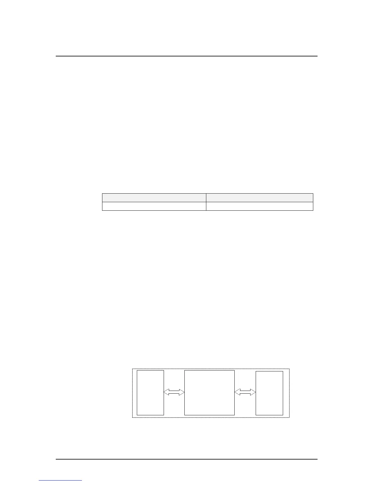
The X-2's circuits and functions are located on three major PCBs as shown in
Figure 2.1.
• Front panel PCB and panel controls
• Rx/Exciter & Control Circuit PCB consisting of:
- RF and Dual synthesizer circuits
- 455 kHz IF and audio circuits
- Microprocessor and peripheral circuits
• PA and Filter PCB.
Front
Panel
PA &
Filters
Receiver\Exciter
and Control
Figure 2.1: X-2 PCB Block Diagram