X-2 Technical Service Manual 8-1
Publication No: 15-02047
8 Appendices
Appendix A: Connectors
The following tables detail the pin connections and functions of the front
and rear connectors. Details are also provided for the cables used for
channel and cloning programming.
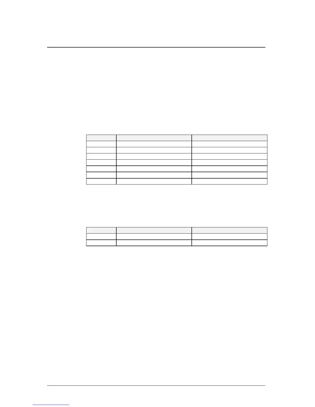
A.1 Microphone
Pin No. Function Signal Levels
1 PTT Ground 0 V
2 PTT Active Active Low
3 Microphone Ground 0 V
4 Microphone Input
50 mV P-P 8 kΩ I/P Imp.
5 Speaker Ground Return * See note below
6 Speaker Audio Output
12 V P-P max. 4Ω min.
7 Speaker Ground 0 V
Table A.1 Microphone Connector pin function.
*Note: Link pin 5 to pin 7 for front panel speaker operation.
A.2 External Loudspeaker
Pin No. Function Signal Levels
Tip Speaker Audio Output
12V P-P max. 4Ω min.Imp.
Sleeve Ground 0 V
Table A.2 External loudspeaker connector pin function.