X2 Technical Service Manual 4-1
Publication No: 15-02047
4 Technical Description
This section of the manual contains a technical description of the X-2
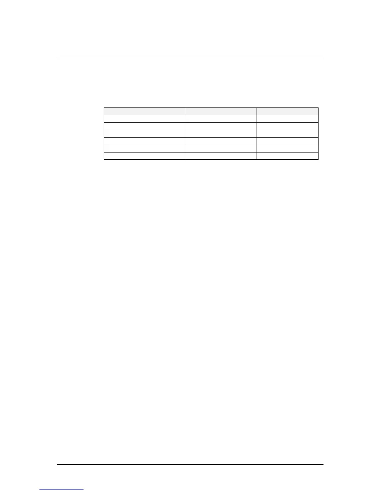
transceiver and should be read together with the drawings shown in
Table 4.1.
Description Circuit Diagram PCB Assembly
Rx/Exciter & Control 04-02907 (3 sheets) 08-04840
-RF and Dual Synthesizer Sheet 1
-455 kHz IF and Audio Sheet 2
-Micro and Peripherals Sheet 3
PA and Filter 04-02908 08-04841
Front Panel 04-02909 08-04842
Table 4.1: Drawing reference Directory
Circuit components on the Rx/Exciter PCB are numbered according to the
following system:
• Sheet 1: 1 to 299
• Sheet 2: 301 to 399
• Sheet 3: 401 to 499
A prompt to use a particular drawing will appear as a symbol in the text.
For example:
104-02907 sheet 1 indicates that you should use sheet 1 of drawing
number 04-02907.
As an additional help a general location guide has been provided to indicate
where to find certain circuit elements described in the text.
For example:
IC302
[D5]
can be found in the vicinity of row D and column 5.