X-2 Technical Service Manual Adjustments 7-11
Publication No: 15-02047
7.11.3 Output Power
To set the output power:
1. Ensure the Exciter output is connected to the PA PCB Assembly (P1
to P2).
2. Select channel position 5 and the USB/LSB to USB. This selects the
channel frequency 3500 kHz, USB, and Antenna 1 O/P.
3. Connect an RMS or PEP Power Meter with a 50 Ω Dummy Load to
Antenna 1 connector.
4. Connect the Oscilloscope via a 47 kΩ resistor to Antenna 1 connector.
Alternatively a Tee piece with an attenuated output of approximately
40 dB can be connected to the oscilloscope.
5. Set the Oscilloscope to the following settings:
• Timebase to 500 µs/division
• Trigger set to auto sweep.
6. Apply the two tone audio via the Test Unit to the microphone socket.
7. Select the Transceiver Test Mode (refer Section 7.5).
8. Select transmit (PTT) and adjust the two tone level for microphone
compression.
9. Adjust the Oscilloscope 'Y' sensitivity for on-screen display and adjust
the trigger for a stationary waveform.
10. Adjust the two tone balance control for good crossover display.
11. Select a value for the Set PWR SOT resistor R14
[C3]
on the PA PCB
for the following output power:
• For Australian use - 100 W PEP. Link X should be fitted to
prevent reduced power at 18 MHz.
• For use outside Australia - 125 W PEP. Link X should not be
fitted. This will allow the output power to fall to about 100 W at
18 MHz.
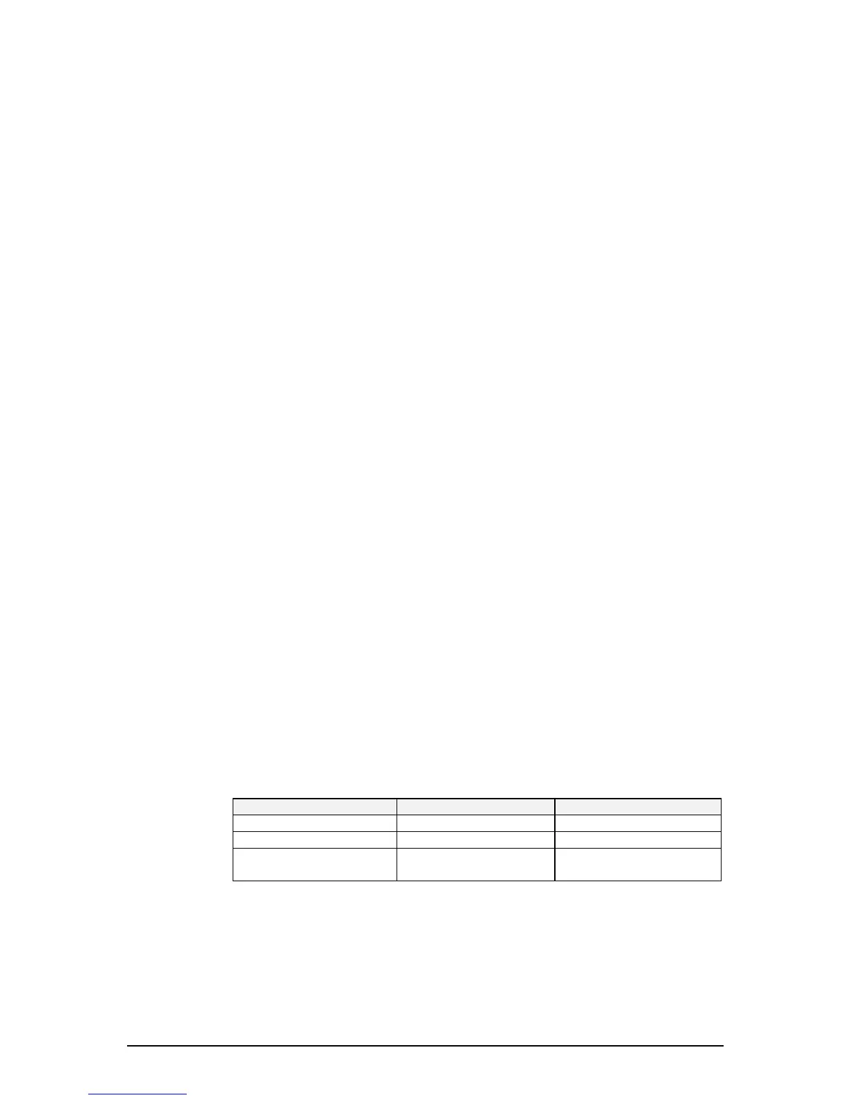
Note: The indicated PEP level with two tone modulation will depend
upon the type of measuring instrument as shown in Table 7.2.
Power output PEP 100 W 125 W
Peak reading meter 100 W 125 W
RMS reading meter 50 W 62.5 W
Average reading meter
(Bird Model 43)
40.5 W 50.6 W
Table 7.2: Power output PEP vs Measuring Instrument
12. Check the two tone waveform is clean and undistorted.
13. The output power is factory set and not likely to be outside the
specified limits. First check there are no faults with the transmitter
circuits before attempting to adjust the power output.