Technical Description 4-2 X-2 Technical Service Manual
Publication No: 15-02047
4.1 Control and Supply Voltages
All switching, except power on, is controlled either directly or indirectly by
the microcontroller located on the Rx/Exciter PCB.
4.1.1 Power
104-02909
When contact S1
[D2]
(part of volume control assembly) on the front panel is
closed, [104-02908] a ground is applied to relay K8
[C10]
on the PA assembly via
interconnecting cables between the Front panel, Rx/Exciter, and the PA
assembly. K8 relay energises and closes contacts K8-1
[D11]
, applying the DC
supply to the Transceiver.
Diode D5 in series with K8 prevents the relay from energising should the
supply be accidentally connected in reverse.
4.1.2 Supply Voltages
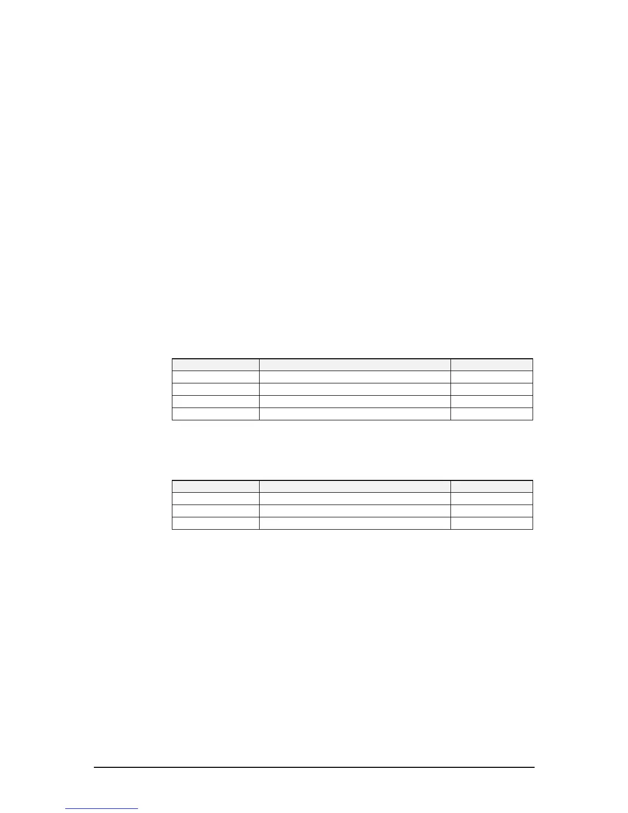
The supply voltages used on the Rx/Exciter PCB are shown in Table 4.2.
Supply Description Regulator
'A' rail unregulated battery supply
'B' rail +10 V regulated supply IC401
+5VA 5 V regulated supply IC3
+5VB 5 V regulated supply IC402
Table 4.2: Rx/Exciter PCB Supply Voltages
The supply voltages used on the PA PCB are shown in Table 4.3.
Supply Description Regulator
'A' rail unregulated battery supply
+5V 5 V regulated supply selected in transmit only IC2
+5V 5 V supply to IC1 V1
Table 4.3: PA PCB Supply Voltages