X-2 Technical Service Manual Adjustments 7-3
Publication No: 15-02047
4. In the Test Mode the channel switch has a 12 position function and the
USB/LSB operates as an extension to the channel switch providing
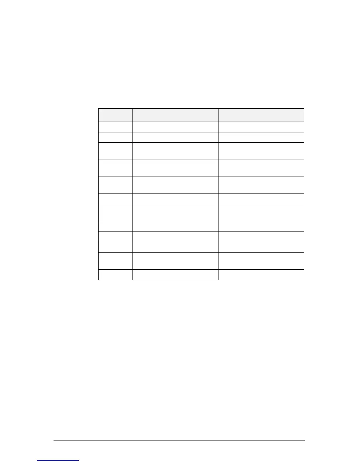
additional channel positions plus other special functions detailed in
Table 7.1.
5. To return to Normal Mode: Switch off Transceiver, remove link from
Link 1, return it to its normal parking position (ground pins of link 1
and 2). The transceiver will now be in its normal operating mode.
Channel
position
Switch to USB
Test frequency and function
Switch to LSB
Test frequency and function
1. 2.00 MHz, USB, Band 1, Ant.1 11.6 MHz, USB, Band 5, Ant.1
2. 2.50 MHz, USB, Band 1, Ant.1 15.5 MHz, USB, Band 5, Ant.1
3. 3.00 MHz, USB, Band 1, Ant.1 17.9 MHz, USB, Band 5, Ant.1
[For USB frequency check]
4. 3.10 MHz, USB, Band 2, Ant.1 17.903 MHz, LSB, Band 5, Ant.1
[For LSB frequency adjust]
5. 3.50 MHz, USB, Band 2, Ant.1 18.0 MHz, USB, Band 5, Ant.2*
For Ant.2 and Talk Power check.
6. 4.70 MHz, USB, Band 2, Ant.1 Not used
7. 4.80 MHz, USB, Band 3, Ant.1 45 MHz filter alignment
[For use with CRO & Sig. Gen]
8. 5.50 MHz, USB, Band 3, Ant.1 VCO1 and 2 centre frequency
9. 7.40 MHz, USB, Band 3, Ant.1 VCO1 and 2 lowest frequency
10. 7.50 MHz, USB, Band 4, Ant.1 VCO1 and 2 highest frequency
11.
*
8.50 MHz, USB, Band 4, Ant.1 45 MHz filter alignment
[Use with Spectrum Analyser]
12.
*
11.5 MHz, USB, Band 4, Ant.1 Not used
Table 7.1: USB/LSB Test Frequencies and Functions
Note: With the exception of channel position 5 - LSB, all other channel
positions have Talk Power Select Off (pin 8 IC405 low). This enables
the two-tone signal to be viewed on the Oscilloscope without the
associated ripple in talk power mode.
*
Channel positions 11 and 12 are not shown on the front panel
escutcheon.