Adjustments 7-6 X-2 Technical Service Manual
Publication No: 15-02047
7.7.1 Alignment - Method 1
The following steps detail the alignment procedure using an Oscilloscope and
a Signal Generator:
1. Select the Transceiver Test Mode (refer to Section 7.5).
2. Select channel position 7 and the USB/LSB to LSB.
3. Connect a 470 µF 16 V electrolytic capacitor in series with an 18 Ω
resistor between TP3
[C3]
and 0 V (-ve of capacitor to 0 V).
4. Remove the shorting link parked on the two ground pins of Link 3 and
4
[D5]
and fit to B-E of N/L TP15. This will open the noise limiter gate.
5. Connect and set a Signal Generator to a frequency of 8.4 MHz
± 100 Hz and an output of 6.3 mV EMF to the receiver input.
6. Connect an Oscilloscope with a 10X probe to TP14
[B7]
. Connect
External Trigger input to Trig
[D4]
Test Point on the PCB. Set the
Oscilloscope to the following settings:
• Channel One to 20mV/division (this equals 0.2V/division with
the attenuation of the 10X probe).
• Timebase to 2ms/division.
• Trigger External. Adjust the trigger for a constant sweep.
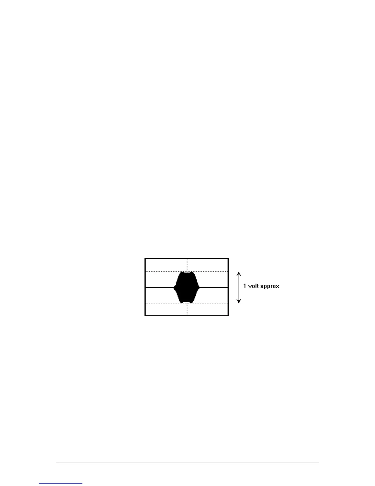
7. Adjust transformers T3
[B6]
and T4 and inductor L10 for minimum ripple
response. (Refer to Figure 7.1.)
Figure 7.1: Ripple Response
8. Remove the shorting link to B-E and return it to its parking position
(ground pins of Link 3 and 4).