X-2 Technical Service Manual Appendices 8-5
Publication No: 15-02047
Appendix C: Engineering Drawings
The Engineering Drawings in this appendix consist of the mechanical and
electrical diagrams required to maintain the X-2 Transceiver.
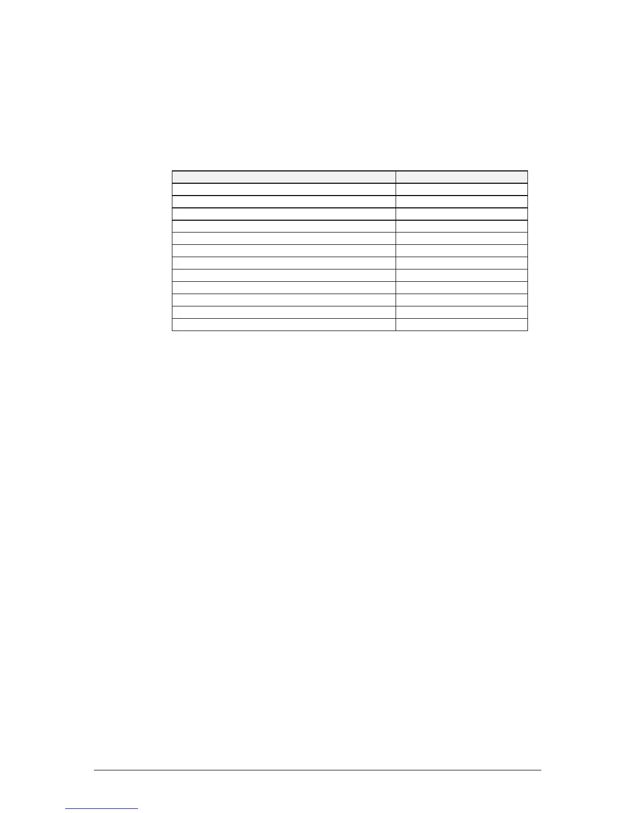
The List of Drawings in Table C.1 details their order of appearance in this
appendix.
Title Drawing No
Mechanical Layout 16-00107
X-2 Block Diagram 03-00876
Interconnection Diagram 04-02910
Front Panel 04-02909
Front Panel PCB Assembly 08-04842
Rx/Exciter & Control (3 Sheets)
- RF & Dual Synthesiser 04-02907 Sheet 1
- 455kHz IF & Audio 04-02907 Sheet 2
- Micro & Peripherals 04-02907 Sheet 3
Receiver/Exciter Assembly 08-04840
PA & Filter 04-02908
PA & Filter PCB Assembly 08-04841
Table C.1 List of Drawings.