INSTALLATION GUIDE FOR mBDA OD SERIES
Copyright - refer to title page
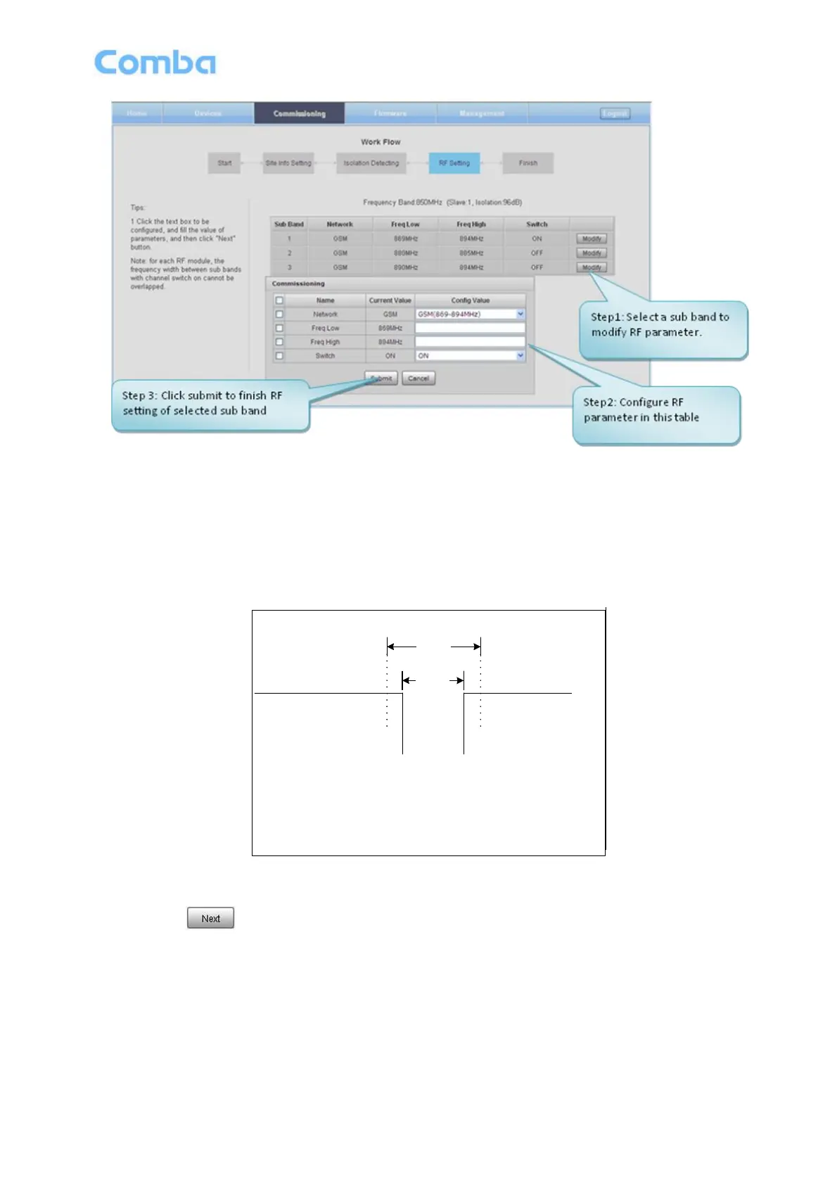
Figure 56: Commissioning Procedure – Sub-band bandwidth and Switch Setting
NOTE: For each RF module, the 3 sub-band bandwidth setting should not be overlap each other, if yes, only
1 sub-band can be turn on, other overlap sub-band is forbidden to switch on by equipment. For GSM system
sub-band bandwidth setting also need comply with follow rules.
GSM system:
The protective frequency edge interval should no less than 800kHz and the minimum interval as illustrated
below.
Band A
N1
N2
Thereinto,
N1:WorkingBand A High Edge Channel No. ,
N2:WorkingBand B Low Edge Channel No. ,
Band B
600kHz
800kHz
Figure 57: The Protective Frequency Edge Interval (GSM system)
Step 6: Click to enter to DL output power setting after finishing sub-band bandwidths and switches
setting.