6 of 40
SECTION 3: INSTALLATION
Installation of Combat HVAC NRG Control must be
done by an electric
ian qualified in the installation of
control systems for heating equipment.
3.1 National Standards and Applicable Codes
All appliances must be installed in accordance with
the latest revision of the applicable standards and
national codes. This refers also to the electric, gas
and venting installation. Note: Additional standards
for installations in public garages, aircraft hangars,
etc. may be applicable.
3.2 Installing the Combat HVAC NRG
Control
Choose a mounting location for control. See Page
2, Section 1.4 and Section 1.6.
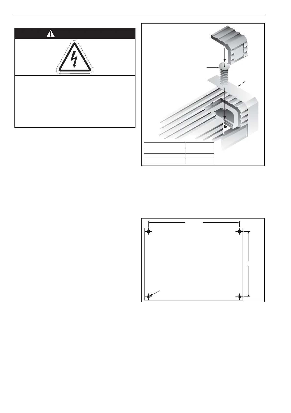
3.2.1 Remove cover of controller by removing four
clips and screws. See Figure 3 for cover detail.
Figure 3: Cover Detail
3.2.2 Disconnect ribbon cable from control PCB
board.
3.2.3 Position controller. Figure 4 shows mounting
hole locations.
Figure 4: Mounting Hole Layout
3.2.4 Remove plastic cable entry plate and carefully
cut suitable holes as required for conduit entry to
control. See Figure 5.
Do not use other entry routes or pass site wiring
over circuit board.
3.2.5 Refit cable entry plate into slot at side of panel.
DANGER
Electrical Shock Hazard
Disconnect electric before service.
Controller must be properly grounded to an
electrical source.
Failure to follow these instructions can
result in death or electrical shock.
Clip Cover
Screw
Lid Assembly
Description Part Number
Clip Cover Plastic 10000701
Screw 10000700
Lid Assembly 10010500
175 mm
140 mm
4 x 5 mm dia
COMBAT HVAC N
RG C
ONTROL
I
NSTALLATION
, O
PERATION
AND
S
ERVICE
M
ANUAL