SECTION 3: INSTALLATION
7 of 40
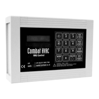
Figure 5: Cable Entry
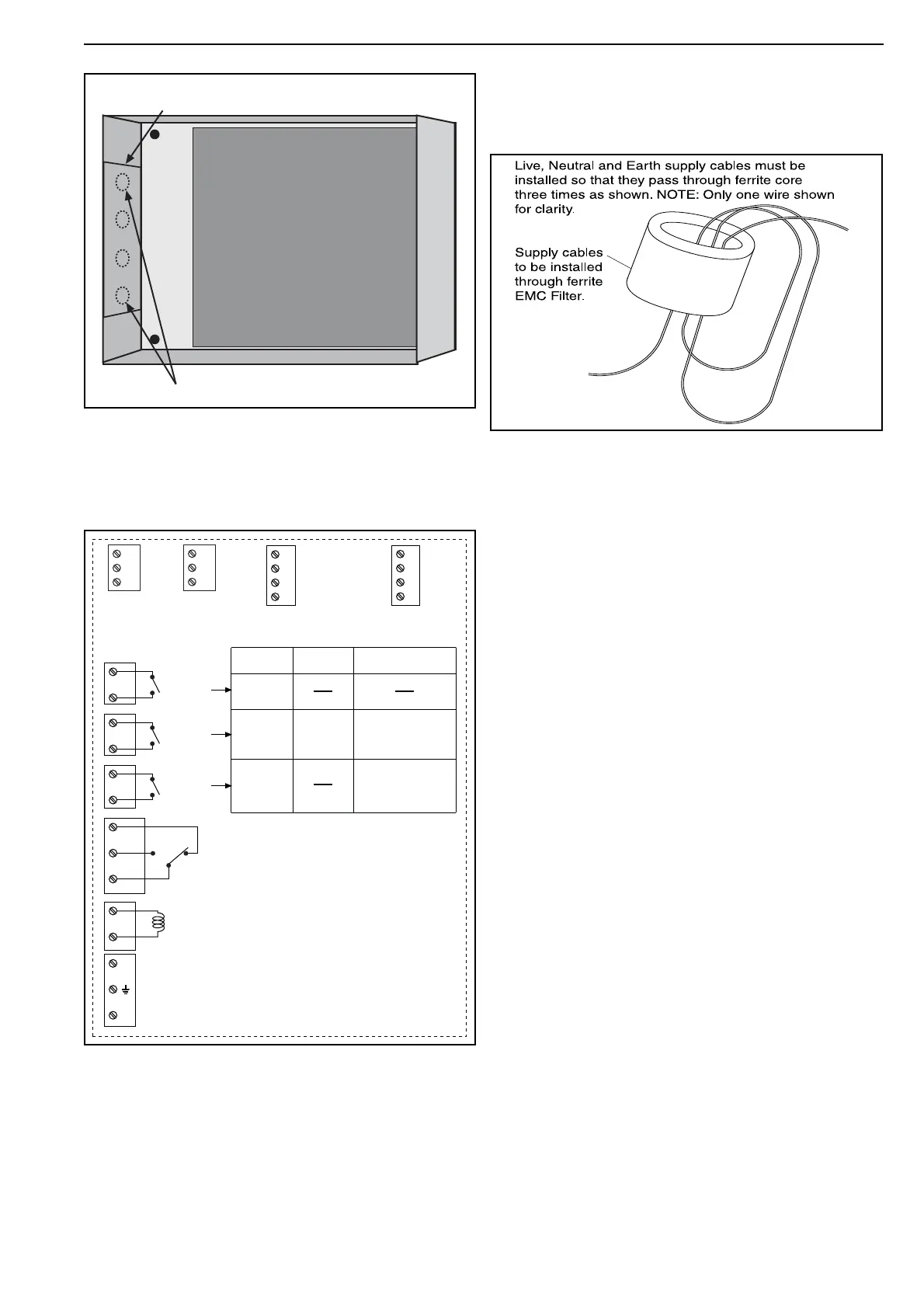
3.2.6 Install electrical wiring in accordance with the
correct wiring diagram in Section 4 to wiring termi-
nals as shown in Figure 6.
Figure 6: Control Terminals and Relay Use
3.2.7 Reconnect ribbon cable to PCB board and
replace cover of control by replacing four screws and
covers as removed on Page 6, Section 3.2.1.
3.3 Electrical Installation Requirements
3.3.1 Panel must have a 230 V 50 Hz supply in
accordance with the appropriate wiring diagram from
Section 4.
3.3.2 Ensure that Live, Neutral and Earth cables are
looped three times through ferrite EMC filter as
shown.
Figure 7: Ferrite EMC Filter
3.3.3 Ens
ure that cables to any low voltage equip-
ment are Belden 8451 shielded cables with shield
connected as shown in the wiring diagrams on Page
9, Section 4.1 through Page 10, Section 4.2.
3.3.4 Lockout Reset
Facilities are available for systems that reset to Live
or reset to Neutral. Look at wiring diagram on each
heater to determine correct system to use for heater
concerned.
Failure to comply will cause permanent damage
to burner control on heater and Combat HVAC
NRG Control.
3.3.5 Network Connections
Optionally controls may linked together as
described on Page 2, Section 1.5. Site wiring is to
be connected and DIP switches s
et as shown on
Page 9, Section 4.1.
3.3.6 Remote Sensors
All s
ensors are electrically connected in the same
way. The use of remote sensors is optional.
One remote temperature sensor will operate
control. For larger heated areas, two remote
temperature sensors may be installed where
control will automatically calculate average of two
readings. See Page 8, Figure 8 through Page 8,
Figure 10.
Position remote sensor/s in accordance with Page
2, Section 1.4 and Page 3, Section 1.6.
See Page 5, Figure 2 for sensor detail.
Circuit Board
Cut suit
able holes
Removable Plastic Entry Plate
12 V
Override
Press' switch
0 -10 V DC
MODULATING
OUTPUT
-
+
S
COMS
PORT
-
+
S
REMOTE
SENSORS
1
+
S
2
INPUTS
-
+
2
1
Lockout
Reset
C
N.O.
N.C.
Burner
Fan
CRV - Multi
Burner Radiant
Unitary
Radiant
Warm Air
Relay 3
Relay 2
Relay 1
Power Supply
230 V 50 Hz
(From Ferrite Filter)
Lockout Signal
230 V 50 Hz
L
N
Fan
Burner or
Low Fire
High
Fire
Burner
N
L