Start Up S0 Network G8-S0/G3-S0-I
12 1.1/1010
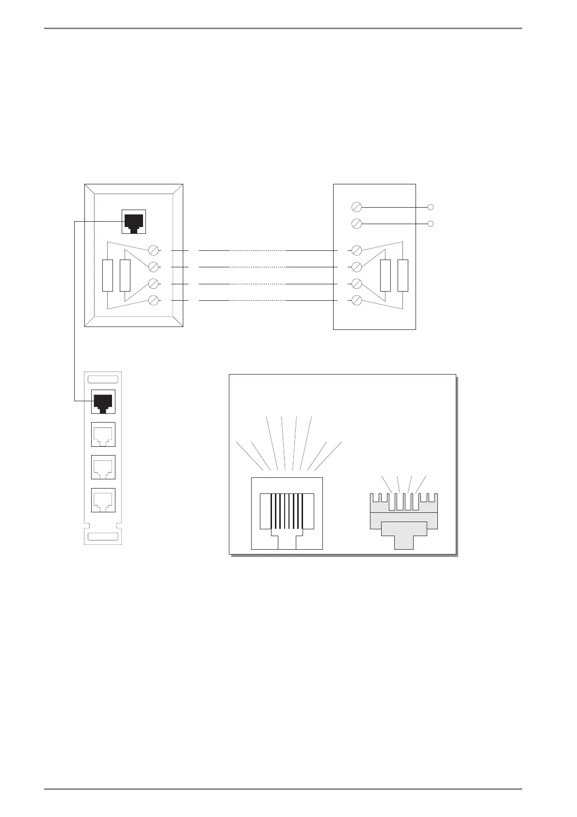
Connection Diagram
For connection to the Intercom Server, the installation board G8A-C has to be used (included in extent
of supply).
If the socket RJ 45 is installed by your Telecom provider, the termination resistors (2 x 100 Ohm) are
usually already integrated.
If the installation board G8A-C is connected directly to the NTBA, no termination resistors are
necessary, but the line may not be longer than 10 m (32.8 ft).
4
/
max. 10 m (33 ft)
3456
7182
100 Ohm
100 Ohm
100 Ohm
100 Ohm
2a
2a
3a2
a
1a
1a
4a1
1b
1b
5b1
b
2b
2b
6b2
3
4
5
6
2a1a
1b2b
1st S0
So cket
2nd S0
not
connected
(not connected
with G3-S0-I )
not
connected
NT
If a twisted pair cable is used,
1a should be twisted with 1b
and 2a with 2b
Plug
Plug connection
G8A-C
Socket RJ45
(Network Termination)
ISDN
connection
S0 Bus 4-wire, max. 150m
(max. 492 ft)
 Loading...